Steel bar truss structure resisting downwarping through upper chord jacking device and application of steel bar truss structure
A technology of steel truss and top extension, applied in the direction of structural elements, building components, building structures, etc., can solve problems such as insufficient economy, waste of manpower and material resources, and increased engineering volume.
- Summary
- Abstract
- Description
- Claims
- Application Information
AI Technical Summary
Problems solved by technology
Method used
Image

Examples
Embodiment 1
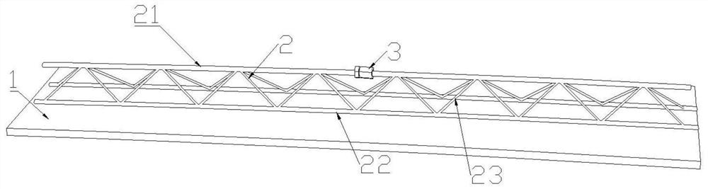
[0046] Such as figure 1 As shown, the present invention proposes a steel bar truss 2 structure that resists downward deflection through an upper chord jacking device 3, including a bottom plate 1, a steel bar truss 2 and a jacking device 3;
[0047]The steel bar truss 2 includes an upper chord bar 21, two lower chord bars 22 parallel to it, and a web steel bar 23 installed between the upper chord bar 21 and the lower chord bar 22; On the surface, the steel bar truss 2 structure is the patent "a U-shaped steel wire binding connected steel bar truss 2 floor deck and floor slab structure", patent authorization publication number: CN 209942003U; in this embodiment, the upper chord bar For solid steel.
[0048] The steel bar truss 2 is arranged on the surface of the bottom plate 1, the upper chord bar 21 of the steel bar truss 2 is interrupted at the mid-span position, and the upper chord bar 21 is interrupted at the position where the jacking device 3 is inserted, such as figur...
Embodiment 2
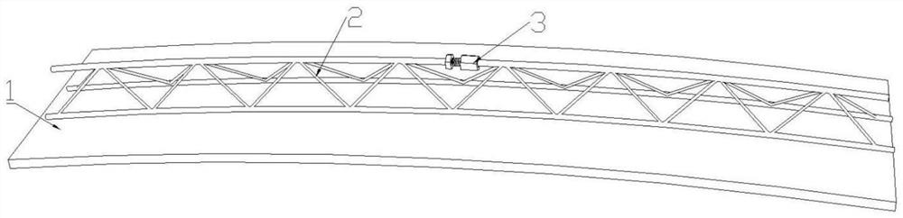
[0053] Such as Figure 5 and Figure 6 As shown, compared with Embodiment 1, the overall structure is the same, and the same parts will not be described in detail. The distinguishing technical feature is that the upper string rib 21 is different from the structure of the top extension device 3. In this embodiment, the upper string rib 21 adopts a hollow steel pipe, so that The stiffness of the upper chord is greatly increased, which can bear greater loads. Especially the stable bearing capacity under compression, with the same cross-sectional area, the stable bearing capacity of hollow steel pipes is more than 2.5 times higher than that of solid steel bars.
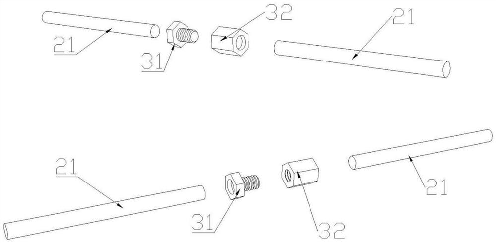
[0054] With the setting of hollow steel pipe, such as Figure 7 As shown, the jacking device 3 is correspondingly modified into a bolt sleeve 31 and a threaded cap 32. The outer surface of one end of the bolt sleeve 31 is provided with external threads, and the inner surface of one end of the threaded cap 32 is provided...
Embodiment 3
[0057] Such as Figure 9 As shown, compared with Embodiment 1 and Embodiment 2, the overall structure is the same, and the difference technology is that the structure of the extension device 3 is different. In this embodiment, the extension device 3 is a threaded cap 33, and the threaded cap 33 is equipped with There are internal threads, and the end surfaces at both ends of the upper string rib 21 are provided with external threads. The threaded cap 33 is inserted into the interrupted position of the upper string rib 21, and through the cooperation between the internal thread and the external thread, the upper string rib 21 The ends at the two ends of the interrupted position are respectively screwed on the two ends of the threaded cap 33; the external threads on the surface of the ends at the two ends of the interrupted position of the upper chord rib 21 are rotated in the opposite direction, and the threaded cap 33 is rotated so that the ends at both ends are reversed. disp...
PUM
 Abstract
Description
Claims
Application Information
 - R&D
- Intellectual Property
- Life Sciences
- Materials
- Tech Scout
- Unparalleled Data Quality
- Higher Quality Content
- 60% Fewer Hallucinations
Browse by: Latest US Patents, China's latest patents, Technical Efficacy Thesaurus, Application Domain, Technology Topic, Popular Technical Reports.
© 2025 PatSnap. All rights reserved.Legal|Privacy policy|Modern Slavery Act Transparency Statement|Sitemap|About US| Contact US: help@patsnap.com