

Engine supercharger surge identification and control method
A control method and supercharger technology, applied in engine control, engine components, combustion engines, etc.
- Summary
- Abstract
- Description
- Claims
- Application Information
AI Technical Summary
Problems solved by technology
Method used
Image

Examples
Embodiment Construction
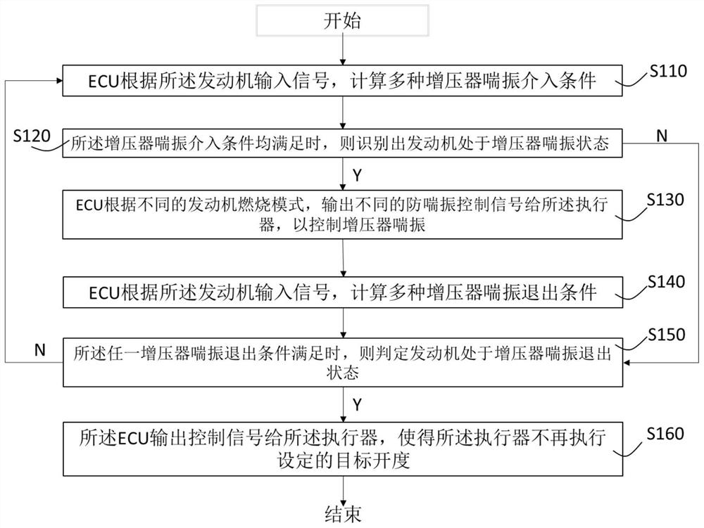
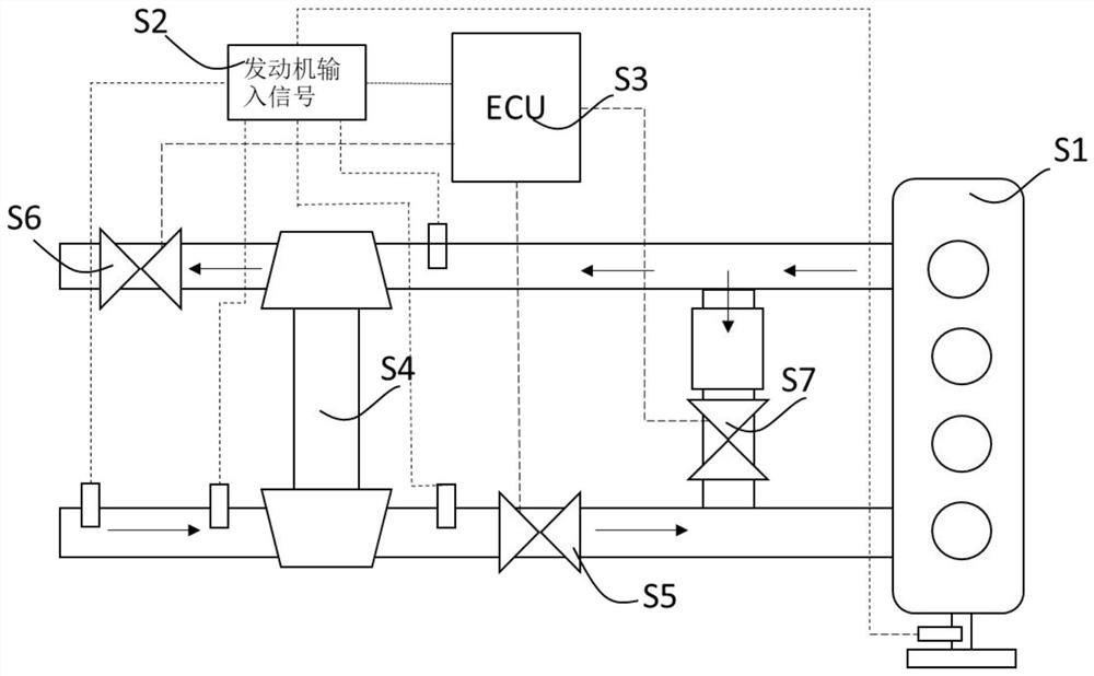
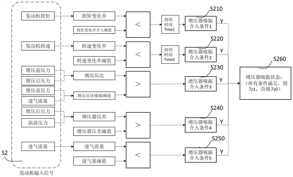
[0034] In this embodiment, a structural diagram of a typical engine intake and exhaust system applicable to an engine supercharger surge identification and control method, as shown in figure 2 As shown, the engine S1 is equipped with an intake throttle valve S5 on the intake pipeline, an exhaust throttle valve S6 on the exhaust pipeline, and a supercharger S4 and EGR between the intake and exhaust pipelines. Valve S7, engine electronic control unit ECU S3 obtains engine input signal S2, and outputs various control signals to intake throttle valve S5, exhaust throttle valve S6, and EGR valve S7 to reduce engine emissions and achieve normal engine operation. Such as image 3 As shown, the engine input signal S2 is the engine speed obtained from multiple sensors, the pressure before supercharging, the pressure after supercharging, the pressure before the swirl, the intake air flow, and the engine torque obtained from the internal model value of the engine electronic control unit...
PUM
 Abstract
Description
Claims
Application Information