Supercharge Your Innovation With Domain-Expert AI Agents!

Liquid sample analysis method, liquid sample analysis device and liquid feeding method

An analysis method and specimen technology, applied in the direction of sampling devices, analysis materials, measuring devices, etc., can solve the problem of not being able to fully observe the formed components

Active Publication Date: 2020-10-20
ARKRAY INC
View PDF9 Cites 0 Cited by
  • Summary
  • Abstract
  • Description
  • Claims
  • Application Information

AI Technical Summary

Problems solved by technology

At this time, if the sample is directly aspirated with the suction part filled with the sheath fluid, the sample will be diluted by the sheath fluid before reaching the flow cell, and the formed components cannot be sufficiently observed in the confluent path of the flow cell.

Method used


Image

  • Liquid sample analysis method, liquid sample analysis device and liquid feeding method
  • Liquid sample analysis method, liquid sample analysis device and liquid feeding method
  • Liquid sample analysis method, liquid sample analysis device and liquid feeding method

Examples


no. 1 Embodiment approach

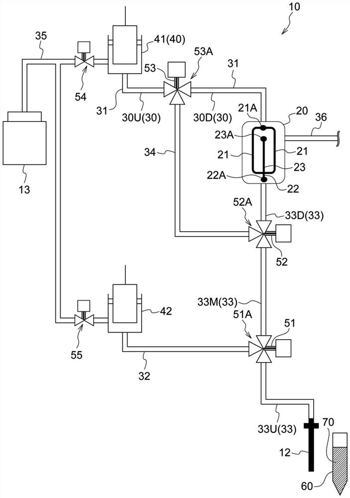
[0079] figure 1 A first embodiment of the analysis device 10 that uses urine as the sample 70 and analyzes the formed components in the urine is schematically shown. In the present embodiment, a sheath fluid supply channel 31 and a sample supply channel 33 are connected as a channel flowing into the flow cell 20 . In addition, a waste liquid path 36 is also connected as a flow path from the flow cell 20 . In addition, for the sake of convenience, in the description of the first embodiment, the analyzer 10 that analyzes the formed components in urine is used, but the sample 70 in the first embodiment is not limited to urine.

[0080] [Structure of Analysis Device 10]

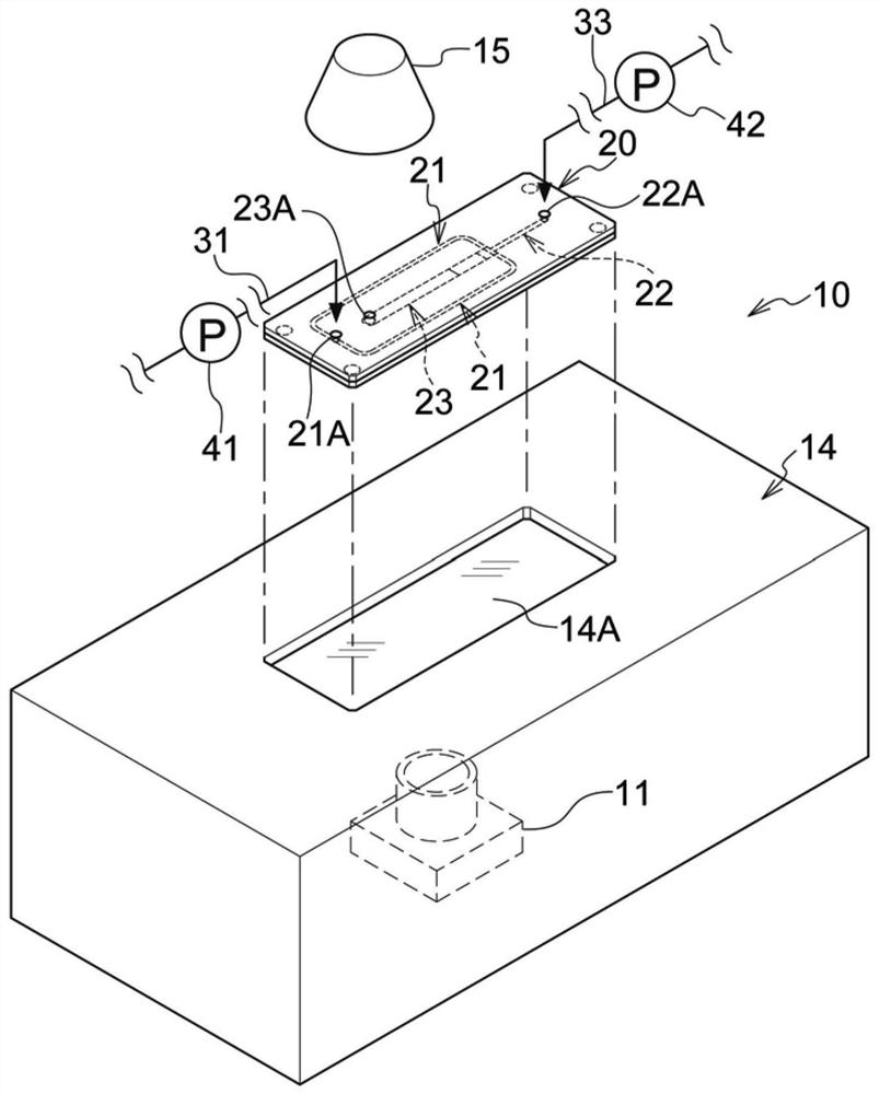
[0081] The flow cell 20 is preferably made of a light-transmitting material (such as synthetic resins such as polymethyl methacrylate resin, cycloolefin polymer resin, polydimethylsiloxane resin, and polypropylene resin, or glass with visible light permeability of More than 90% of the material) is formed. The...

no. 2 Embodiment approach

[0119] Figure 13 A second embodiment of an analysis device 10 that analyzes formed components in urine using urine as a sample 70 is schematically shown. The second embodiment differs from the first embodiment in that a third switching unit 53 is provided on the sample extruding channel 32 , and the branch channel 34 connects the sample supply channel 33 and the sample extruding channel 32 . connect them. In this embodiment, as in the first embodiment, a sheath fluid supply channel 31 and a sample supply channel 33 are connected as channels for flowing into the flow cell 20 . In addition, a waste liquid path 36 is also connected as a flow path from the flow cell 20 . In addition, for the sake of convenience, in the description of the second embodiment, the analyzer 10 that analyzes the formed components in urine is used, but the sample 70 in the second embodiment is not limited to urine.

[0120] [Structure of Analysis Device 10]

[0121] The structure of the flow cell 20...


PUM


Abstract

The invention discloses a liquid sample analysis method, liquid sample analysis device and a liquid feeding method. The liquid sample analysis method including communicating a specific flow path (30)with an aspirator (12) via a branch flow path (34), aspirating air (90) from the aspirator (12), aspirating a liquid sample (70) into the sample supply path (33) from the aspirator (12) so that an entire amount of the aspirated air (90) is accommodated in the branch flow path (34), communicating a sample extrusion path (32) with a sample port (22A), communicating a sheath fluid supply path (31) with a sheath fluid port (21A), and isolating the branch flow path (34) from both the sample supply path (33) and the specific flow path (30), extruding the liquid sample (70) in the sample supply path(33) so as to inflow into the sample flow path (22) by causing a sheath fluid (80) to inflow into the sheath fluid flow path (21) from the sheath fluid supply path (31) and causing the sheath fluid (80) to inflow into the sample supply path (33) from the sample extrusion path (32).

Description

technical field [0001] The present invention relates to a sample analysis method and a sample analysis device using a flow cell. Background technique [0002] Patent Document 1 and Patent Document 2 disclose a flow cell having the following parts: a sheath fluid flow path for bifurcating the sheath fluid flowing in from the sheath fluid inlet; a sample flow path through which the sample flows; and a confluence path. , at the merging path, the two parts of the sheath fluid flow path and the sample flow path are merged, and the formed components contained in the sample are photographed. [0003] Patent Document 1: Japanese Patent Laid-Open No. 2018-112516 [0004] Patent Document 2: Japanese Patent Laid-Open No. 2019-7893 [0005] At the end of the sample supply path that supplies the sample to the flow cell as described above, a suction unit such as a nozzle that sucks the sample is provided. Before the measurement of the sample, the sheath fluid is usually filled from the...

Claims


Application Information

Patent Timeline
Patent Type & Authority Applications(China)
IPC IPC(8): G01N33/52G01N35/10
CPCG01N33/52G01N35/1009G01N35/1097G01N15/1404G01N2015/1006G01N15/1459G01N33/4915G01N33/493G01N2015/1413G01N2001/002G01N2001/1418G01N15/1409G01N1/14G01N21/05
Inventor 太田进一中岛真也
Owner ARKRAY INC
Features
  • R&D
  • Intellectual Property
  • Life Sciences
  • Materials
  • Tech Scout
  • Unparalleled Data Quality
  • Higher Quality Content
  • 60% Fewer Hallucinations
Learn More