
Multi-specified-height CCD imaging system and method based on trapezoidal lens

An imaging system and lens technology, applied in the field of atmospheric optical detection and optical imaging, can solve problems such as difficulty in accurately guaranteeing angular accuracy

Active Publication Date: 2020-10-20
HEFEI INSTITUTES OF PHYSICAL SCIENCE - CHINESE ACAD OF SCI
View PDF8 Cites 0 Cited by
  • Summary
  • Abstract
  • Description
  • Claims
  • Application Information

AI Technical Summary

Problems solved by technology

[0004] In order to solve the problem of how to determine the detection height when the detection surface of the CCD is tilted and how to determine the detection height in the original DCIM detection scheme, the present invention provides a trapezoidal lens-based multi-specified height CCD imaging system and method

Method used


Image

  • Multi-specified-height CCD imaging system and method based on trapezoidal lens
  • Multi-specified-height CCD imaging system and method based on trapezoidal lens
  • Multi-specified-height CCD imaging system and method based on trapezoidal lens

Examples


Embodiment 1

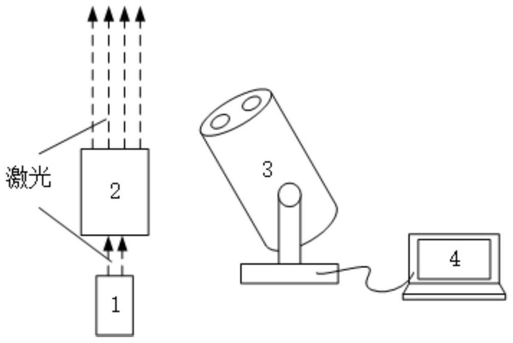
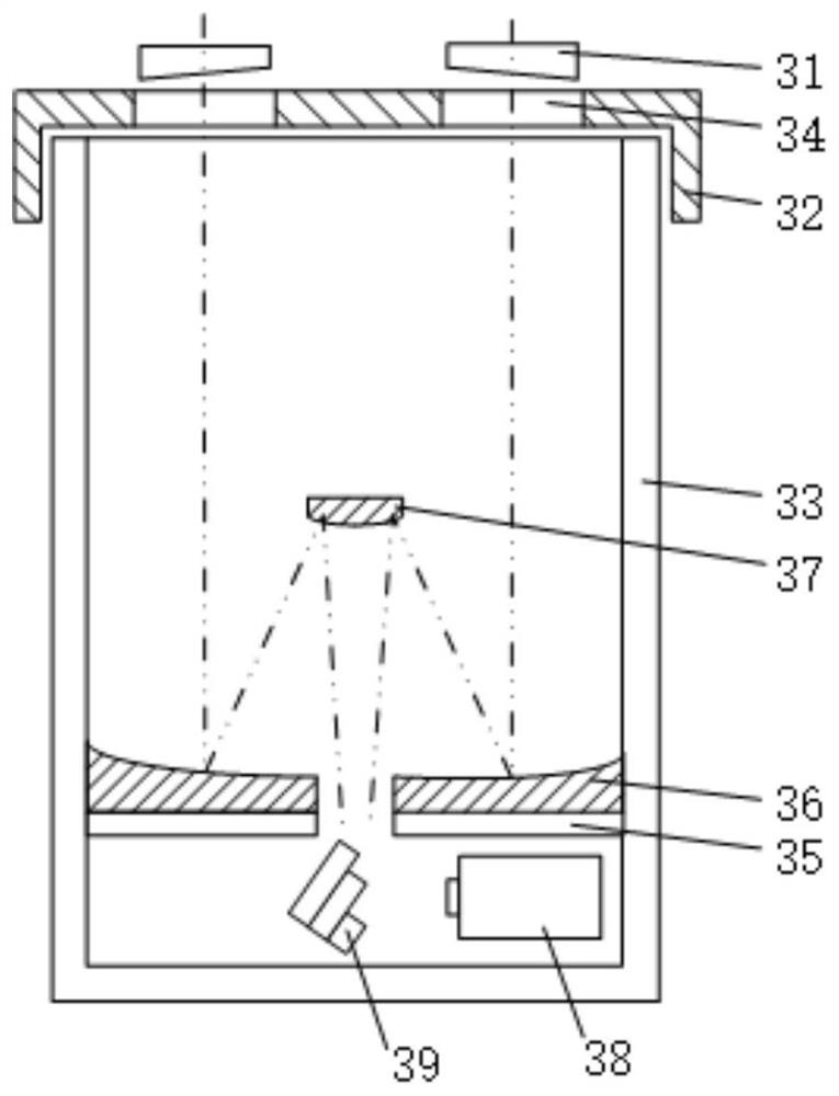
[0027] Such as Figure 1-2 As shown, a CCD imaging system with multiple designated heights based on a trapezoidal lens includes a laser transmitter 1 , an emission beam expander and collimator 2 , a receiving device 3 and a computer 4 . The laser emitter 1 is a continuous light laser emitter.

[0028] Such as figure 1 As shown, the laser transmitter 1 is separated from the receiving device 3 by a certain distance, and the laser generated by the laser transmitter 1 passes through the emitting beam expander 2 to form a collimated beam and emits it into the atmosphere. The device 3 receives the echo photons generated by the collimated beam through two sub-apertures and forms an image. The receiving device 3 is connected to the processing computer 4, and the imaging data is output to the processing computer 4. The processing computer 4 Process the imaging data, and finally output it through the screen.

[0029] Such as figure 2 As shown, the receiving device 3 includes a wedg...

Embodiment 2

[0034] Using the method of a multi-specified height CCD imaging system based on trapezoidal lenses described in Embodiment 1, wherein the rectangular lenses are arranged in a stepped shape, and the relative heights and angles of the lenses are pre-calculated, pre-calculated The steps are as follows:

[0035] 1) Predetermine the number of imaging points and the relative height of each imaging point relative to the emission position.

[0036] 2) According to the object-image relational expression at each height point, determine the actual image distance of each imaging point.

[0037] 3) Calculate and determine the relative height and angle of the trapezoidal lens according to the actual image distance of each imaging point, so as to compensate for the imaging distance difference of imaging points at different heights.

[0038] Specifically, the high-reflection band range of the high-reflection film of the rectangular lens coated with the high-reflection film covers the laser b...


PUM


Abstract

The invention relates to the field of atmospheric optical detection and optical imaging, and in particular relates to a multi-specified-height CCD imaging system and method based on a trapezoidal lens. The system comprises a laser transmitter and a receiving device, the receiving device comprises a receiving telescope and a CCD camera, and the receiving telescope comprises a trapezoidal lens; laser emitted by the laser emitter is reflected by the trapezoidal lens, and reflected light is captured by the detection end of the CCD camera; the trapezoidal lens is composed of n rectangular lenses, the reflecting surfaces of the rectangular lenses are plated with high-reflectivity films, the rectangular lenses are arranged in a stepped manner, and n is greater than or equal to 2. According to theinvention, the problem that in an original DCIM detection scheme, in order to enable a CCD detection surface to coincide with a focal plane formed for the height, when the CCD detection surface needsto be obliquely placed at a specific angle, the angle precision is difficult to accurately guarantee is solved.

Description

technical field [0001] The invention belongs to the field of atmospheric optical detection and optical imaging, in particular to a trapezoidal lens-based multi-designated-height CCD imaging system and method. Background technique [0002] During the transmission of laser in the atmosphere, random fluctuations will occur on its transmission path due to the influence of atmospheric turbulence, which will cause flickering, energy redistribution, random drift and other phenomena on the beam. The size of the atmospheric coherence length can reflect the intensity of the influence of the laser on the transmission path by the atmospheric turbulence, which is of great significance to the study of laser atmospheric transmission. [0003] Real-time measurement of atmospheric coherence length by laser radar and other equipment is relatively direct and convenient. Laser radar measurement can measure different paths and is less affected by weather conditions. Representatives include diffe...

Claims


Application Information

Patent Timeline
Patent Type & Authority Applications(China)
IPC IPC(8): G01S17/95G01S7/481G01S7/48G01S7/497
CPCG01S17/95G01S7/481G01S7/4802G01S7/497Y02A90/10
Inventor 靖旭谭逢富侯再红何枫张巳龙秦来安王浩
Owner HEFEI INSTITUTES OF PHYSICAL SCIENCE - CHINESE ACAD OF SCI
Learn More