Laser module
A laser module, laser technology, applied in lasers, laser devices, semiconductor lasers, etc., to achieve the effect of improving coupling efficiency
- Summary
- Abstract
- Description
- Claims
- Application Information
AI Technical Summary
Problems solved by technology
Method used
Image

Examples
no. 1 Embodiment approach 〕
[0020] (Structure of laser module)
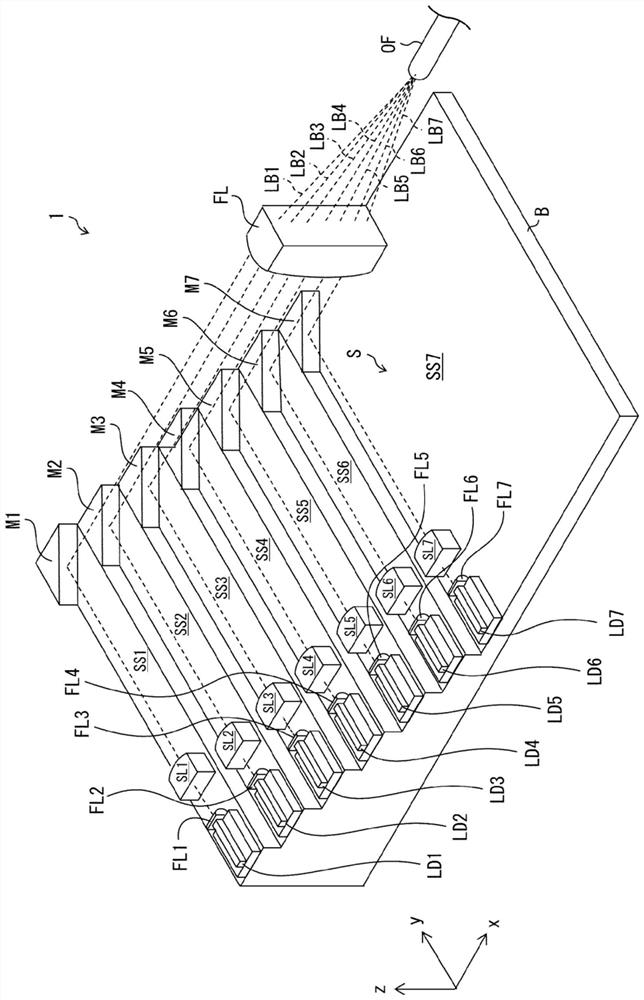
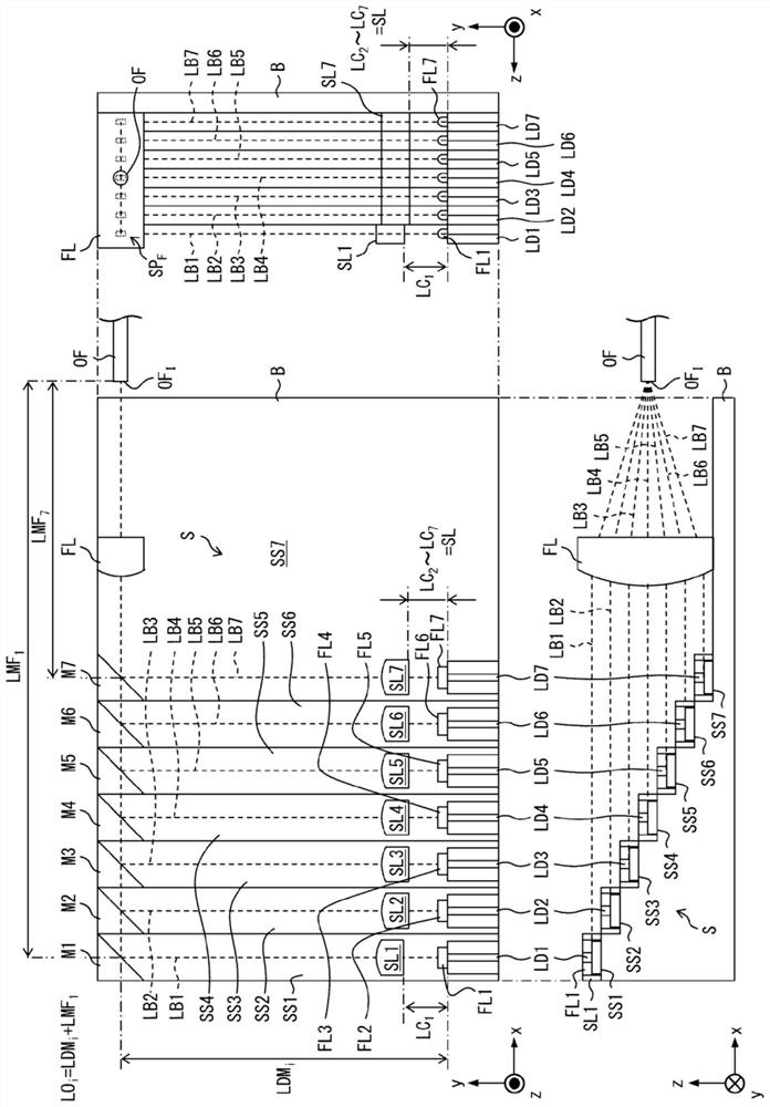
[0021] refer to figure 1 The configuration of the laser module 1 according to the first embodiment of the present invention will be described. figure 1 It is a perspective view of the laser module 1 .
[0022] Such as figure 1 As shown, the laser module 1 has 7 laser diodes LD 1 ~LD 7 , 7 F-axis collimating lenses FL 1 ~FL 7 , 7 S-axis collimating lenses SL 1 ~SL 7 , 7 mirrors M 1 ~ M 7 , a condenser lens FL and an optical fiber OF. Laser diode LD 1 ~LD 7 , F-axis collimator lens FL 1 ~FL 7 , S-axis collimator lens SL 1 ~SL 7 , Mirror M 1 ~ M 7 And the condenser lens FL is mounted on the bottom plate B of the casing of the laser module 1 . The optical fiber OF penetrates the side wall of the housing of the laser module 1, and will include the incident end face OF I The inner end is guided into the housing of the laser module 1 . In addition, in figure 1 In , the illustration of the side wall of the housing of the l...
no. 1 Embodiment
[0085] refer to Figure 5 A laser module 1 as a first embodiment of the present invention will be described. The laser module 1 of the present embodiment takes figure 1 The shown structure of the laser module 1 is based on an increase in the number of unit optical systems from n=7 to n=13.
[0086] Figure 5 (a) represents the coupling efficiency and collimation length LC in the unit optical system included in the laser module 1 of the present embodiment. i The associated coordinate map of . Figure 5 (b) represents a preferred collimation length LC for each unit optical system included in the laser module 1 of this embodiment. i coordinate diagram.
[0087] Depend on Figure 5 (a) can be seen by making each collimation length LC i (i=1, 3, 7, 10, 13) varies within the range of 9 mm to 10.5 mm, so that each laser LB i The coupling efficiency changes. according to Figure 5 As a result of (a), for each case of i=1, 3, 7, 10, 13, the optimal collimation length LC is o...
no. 2 Embodiment
[0091] refer to Figure 6 A laser module as a second embodiment of the present invention will be described. The laser module 1 of the present embodiment takes Figure 7 Based on the structure of the laser module 101 shown, after increasing the number of unit optical systems from n=7 to n=13, the S-axis collimator lens SL i The curvature r i obtained by change.
[0092] Figure 6 (a) represents the coupling efficiency and curvature r in the unit optical system included in the laser module of this embodiment i The associated coordinate map of . Figure 6 (b) represents the preferred curvature r for each unit optical system included in the laser module 1 of the present embodiment. i coordinate diagram.
[0093] Depend on Figure 6 (a) can be seen: by making each curvature r i (i=1, 3, 7, 10, 13) varies within the range of 6.2 mm to 6.9 mm, so that each laser LB i The coupling efficiency changes. according to Figure 6 As a result of (a), for each case of i=1, 3, 7, 10,...
PUM
 Abstract
Description
Claims
Application Information
 - R&D Engineer
- R&D Manager
- IP Professional
- Industry Leading Data Capabilities
- Powerful AI technology
- Patent DNA Extraction
Browse by: Latest US Patents, China's latest patents, Technical Efficacy Thesaurus, Application Domain, Technology Topic.
© 2024 PatSnap. All rights reserved.Legal|Privacy policy|Modern Slavery Act Transparency Statement|Sitemap