Agricultural pulverizer

A pulverizer, agricultural technology, applied in the agricultural field, can solve problems such as clogging, uneven soybean particle size, and single structure

Inactive Publication Date: 2020-10-23
广州赢帝工业设计有限公司
View PDF10 Cites 1 Cited by
  • Summary
  • Abstract
  • Description
  • Claims
  • Application Information

AI Technical Summary

Problems solved by technology

[0003] Aiming at the problem that the structure of the above-mentioned existing pulverizer is single, during the process of screening and pulverizing the grain particles, it is easy to accumulate and block t

Method used


Image

  • Agricultural pulverizer
  • Agricultural pulverizer
  • Agricultural pulverizer

Examples


Embodiment 1

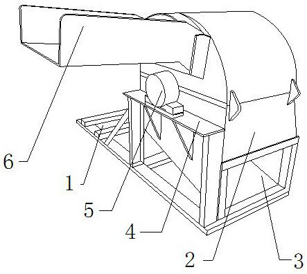
[0026] Such as Figure 1-Figure 6 Shown:

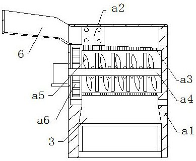
[0027] The invention provides an agricultural pulverizer, the structure of which comprises a bottom frame 1, a pulverizer 2, a discharge port 3, a fixed table 4, a motor 5, and a feed plate groove 6, and the discharge port 3 is nested and connected to At the bottom right of the pulverizer 2, the motor 5 is bolted to the top of the fixed table 4, the pulverizer 2 is welded to the top of the bottom frame 1, and the fixed table 4 is embedded and connected to the angle between the bottom frame 1 and the pulverizer 2 The feed plate groove 6 is bolt-connected to the front upper end of the pulverizer 2, and the motor 5 is embedded and connected to the front end of the pulverizer 2. The pulverizer 2 mainly includes a body a1, a beating device a2, a sieve plate a3, The rotating shaft a4, the crushing paddle a5, and the anti-slip device a6, the rotating shaft a4 is movably engaged on the right side of the motor 5, the crushing paddle a5 is emb...

Embodiment 2

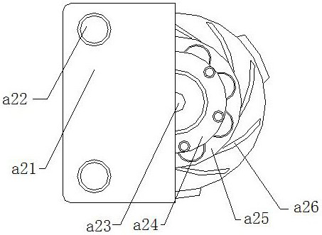
[0035] Such as Figure 7-Figure 8 Shown:

[0036] The present invention provides an agricultural pulverizer. The anti-skid device a6 mainly includes a joint plate c1, a blocking plate c2, and a rotating anti-slip wheel c3. The rotating anti-slip wheel is movably engaged inside the joint plate c1, and the blocking plate c2 Embedded and connected in front of the joint plate c1, the rotating anti-slip wheel c3 is connected to the rotating shaft a4, and the anti-slip device a6 is nested and connected outside the rotating shaft a4 to increase the rotation rate of the rotating shaft a4 so that it can better carry out grain grains crushing work.

[0037] Wherein, the rotating anti-skid wheel c3 mainly includes a fixed sleeve c31, a wheel cover c32, a roller c33, and a sleeve shaft c34. The wheel sleeve c32 is nested and connected outside the roller c33, and the sleeve shaft c34 is installed on the Inside the fixed sleeve c31, there are three rollers c33 in total, and they evenly su...


PUM


Abstract

The invention discloses an agricultural pulverizer. The agricultural pulverizer structurally comprises a bottom frame, a pulverizer body, a discharging port, a fixing table, a motor and a feeding plate groove, wherein the motor is fixedly connected to the front end of the pulverizer body in an embedded mode, the pulverizer body comprises a machine body, a flapping device, a sieving plate, a rotating shaft, pulverizing blades and an anti-skid device, the flapping device is connected to the upper front portion of the sieving plate through bolts, and the anti-skid device is movably clamped to thefront end of a rotating shaft. According to the agricultural pulverizer, an inner wheel and an auxiliary wheel are driven to rotate through an axis, the flapping device rotates clockwise for flapping, a beating ball is nested in a combined arc plate, beating of the beating ball can rebound and buffer, the situation that equipment is jammed due to the fact that a large number of grain particles are thrown in is avoided, when the rotating shaft rotates, idler wheels are movably clamped between a fixed sleeve and a sleeve shaft, the three idler wheels uniformly surround the outer part of the sleeve shaft, and wheel sleeves of the idler wheels are engaged and matched between the fixed sleeve and the sleeve shaft, so that the anti-skid capability is achieved, and the condition that a rotatinganti-skid wheel rotates reversely is avoided.

Description

technical field [0001] The present invention relates to the field of agriculture, and more specifically, relates to an agricultural pulverizer. Background technique [0002] The main function of the pulverizer is to crush large-sized solid particles into smaller-sized particles. Soybean is one of the important food crops in China. It is often used to make various soybean products, extract soybean oil, brew soy sauce and extract protein. Bean dregs or ground into Coarse soybeans are also commonly used in poultry and livestock feed. Due to the single structure of the existing grinder, during the process of screening and crushing grain particles, it is easy to accumulate and block the equipment feeding trough due to uneven particle size or a large amount of feeding, resulting in crushing The crushing effect of the machine is insufficient. Contents of the invention [0003] Aiming at the problem that the structure of the above-mentioned existing pulverizer is single, during t...

Claims


Application Information

Patent Timeline
IPC IPC(8): B02C9/00B02C11/00
CPCB02C9/00B02C11/00
Inventor 付瑜
Owner 广州赢帝工业设计有限公司
Why Eureka
Try Eureka