High-efficiency spray structure of environment-friendly spray tower

A spray tower, an environmentally friendly technology, applied in the field of high-efficiency spray structures, can solve problems such as leakage, reduced purification efficiency, and shaking of connections

Inactive Publication Date: 2020-10-23
泉州市琼鑫工业设计有限公司
View PDF9 Cites 1 Cited by
  • Summary
  • Abstract
  • Description
  • Claims
  • Application Information

AI Technical Summary

Problems solved by technology

[0003] When the spraying mechanism is in use, because the spraying mechanism is impacted by the circulating water tank, it is easy to cause the connection to shake, which in turn caus

Method used


Image

  • High-efficiency spray structure of environment-friendly spray tower
  • High-efficiency spray structure of environment-friendly spray tower
  • High-efficiency spray structure of environment-friendly spray tower

Examples


Embodiment 1

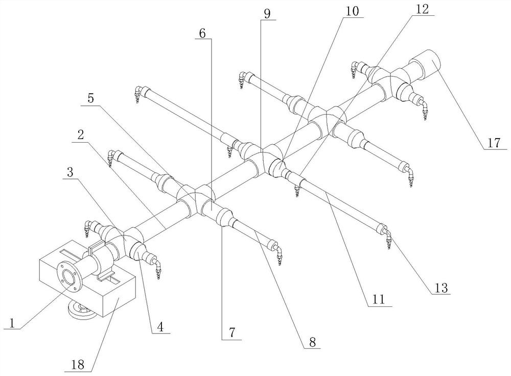
[0029] see Figure 1-2 , the present invention provides an efficient spraying structure of an environment-friendly spray tower through improvement, including a flange 1 and a reinforcement device 18, the right end of the flange 1 is attached to the left end of the water pipe 2, and the water pipe 2 is connected to the first connector 3 The middle part is plugged in, and the water pipe 2 is plugged in the middle part of the second connector 5, the front end of the first connector 3 is plugged into the rear end of the first connecting cover 4, and the front end of the second connector 5 is plugged into the rear end of the first connecting pipe 6 , the front end of the first connection pipe 6 is connected to the rear end of the second connection cover 7, the front end of the second connection cover 7 is connected to the rear end of the second connection pipe 8, the middle part of the water pipe 2 is provided with a third connector 9, and the third connector 9 The front end is con...

Embodiment 2

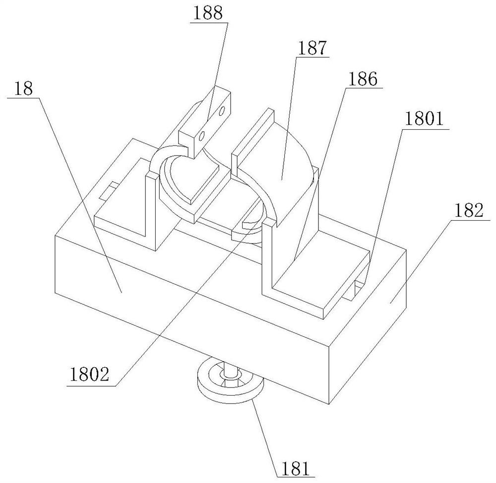
[0034] The present invention provides a high-efficiency spraying structure of an environment-friendly spraying tower through improvement. The lower end of the L-shaped plate 186 is offset against the upper end of the housing 182, which is conducive to sliding installation with the chute 1801 and the stability of the lifting device. The lower end of the slide rail 1853 Fastened to the inner front end of the housing 182, it is beneficial to realize the fixing effect, and the upper end of the sliding plate 1856 is slidably installed with the upper end of the housing 182, which is beneficial to improving the stability of the sliding plate 1856 when moving.

[0035] The present invention provides a high-efficiency spray structure of an environment-friendly spray tower through improvement, and its working principle is as follows;

[0036] First, before use, the first connector 3, the second connector 5 and the third connector 9 are connected to the water pipe 2 in sequence, and then ...


PUM

PropertyMeasurementUnit
Thicknessaaaaaaaaaa

Abstract

The invention discloses a high-efficiency spray structure of an environment-friendly spray tower. The high-efficiency spray structure comprises a flange, a water pipe, a first communicating vessel, afirst connecting cover, a second communicating vessel, a first connecting pipe, a second connecting cover, a second connecting pipe, a third communicating vessel, a third connecting cover, a third connecting pipe, a sleeve, a port, a bent pipe, a connector, a nozzle, a fixed column and a reinforcing device. According to the high-efficiency spray structure, the reinforcing device is arranged at theleft end of the water pipe, a hand wheel drives a gear to rotate, the gear drives a rack to drive a first sliding block to be installed at the upper end of a sliding rail in a sliding mode through afirst connecting plate, and the effect of improving stability is achieved; then an L-shaped plate drives a clamping frame to clamp an external pipeline, and shaking generated at the connecting position is reduced, so that liquid leakage is avoided, the spraying effect is guaranteed, and the purification efficiency is improved; and a fixing plate is driven to move through the clamping frame, the fixing plate drives an inserting rod to penetrate through a through hole to be connected with a clamping block in a buckled mode, then the reinforcing effect is achieved, and the stability of the deviceis improved.

Description

technical field [0001] The invention relates to the related field of spray structure, in particular to an efficient spray structure of an environment-friendly spray tower. Background technique [0002] As a pretreatment device in waste gas treatment, the spray tower plays a key role in dust removal and cooling, and plays a key role in many waste gas treatments. The existing spray tower has the advantages of environmental protection, and is mainly composed of circulating water tanks, The tower body, air inlet section, spray mechanism, mist eliminator, exhaust port, inspection port, etc. The exhaust gas is introduced into the spray tower through the air duct, and after being sprayed by the spray mechanism, the exhaust gas and the liquid fully contact and react, and the exhaust gas After purification, it will be dehydrated and demisted by the demisting layer, and then discharged into the atmosphere by the fan. [0003] When the spraying mechanism is in use, because the sprayin...

Claims


Application Information

Patent Timeline
IPC IPC(8): B05B15/60B01D47/06B01D53/78
CPCB01D47/06B01D53/78B05B15/60
Inventor 蔡研研邓春华
Owner 泉州市琼鑫工业设计有限公司
Why Eureka
Try Eureka