
Workpiece surface paint spraying equipment for machining

A technology of workpiece surface and painting equipment, which is applied in the direction of paint spraying room, pretreatment surface, surface coating liquid device, etc., can solve the problem that cannot meet the quality requirements of large-volume workpieces, cannot be sprayed, and cannot be stably and reliably clamped fixed

Pending Publication Date: 2020-10-23
陶唤唤
View PDF0 Cites 4 Cited by
  • Summary
  • Abstract
  • Description
  • Claims
  • Application Information

AI Technical Summary

Problems solved by technology

[0004] Although the paint spraying device of the above technical solution can simply paint the workpiece and avoid the manual use of the spray gun, the painting efficiency has been improved to a certain extent, but it cannot be used in large stroke ranges for larger mechanical workpieces. Effective and uniform spraying treatment is carried out on the designated position of the large-volume workpiece, and the workpiece cannot be clamped and fixed stably and reliably, which makes its use have obvious limitations, which in turn makes the effect of its spraying poor and cannot meet the requirements Quality requirements for spraying paint on the surface of large-volume workpieces

Method used


Image

  • Workpiece surface paint spraying equipment for machining
  • Workpiece surface paint spraying equipment for machining
  • Workpiece surface paint spraying equipment for machining

Examples


Embodiment 1

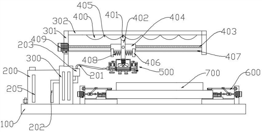
[0035] Such as figure 1 As shown, in the embodiment provided by the present invention, a workpiece surface painting equipment for mechanical processing, the painting equipment includes an equipment base 100, and a hydraulic telescopic cylinder 300 is fixedly arranged on one side of the equipment base 100, and the The telescopic end of the top of the hydraulic telescopic cylinder 300 is fixedly provided with a support column 301, the top of the support column 301 is fixedly equipped with a support frame 302, and the lower surface of the support frame 302 is uniformly and fixedly provided with a plurality of arc-shaped protrusions 400, A guide groove 405 is formed between two adjacent arc-shaped protrusions 400; the lower part of the support column 301 is supported and rotated to be provided with a support screw 403, and a support slider 404 is sleeved on the support screw 403 through a threaded connection. The bottom surfaces of both sides of the support slider 404 are fixedly ...

Embodiment 2

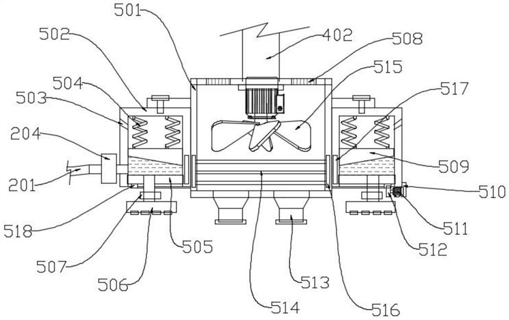
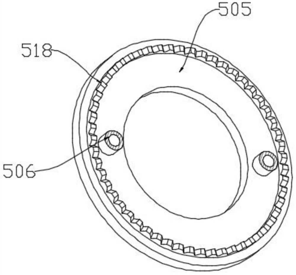
[0041] The difference from Example 1 is that please continue to refer to figure 1 , figure 2 , image 3 and Figure 7 , in the embodiment provided by the present invention, the structure of the painting device 500 is also specifically defined.

[0042] Specifically, in the embodiment provided by the present invention, the painting device 500 includes a motor base 501 fixedly installed at the bottom end of the support pendulum 402, and the outer ring of the motor base 501 is fixedly sleeved with a ring Box 502, the bottom opening of the annular box 502 is sealed and rotated with a liquid distribution rotating disk 505, and the liquid distribution rotating disk 505 is provided with a paint atomizer for spraying paint liquid in the annular box 502 Nozzle 506, and the liquid inlet part of the paint atomization nozzle 506 is also provided with a booster valve 507 to enhance the effect of the paint atomization nozzle 506 spraying paint; in addition, the bottom outer ring of the ...

Embodiment 3

[0050] Different from Embodiment 2, this embodiment of the present invention also includes a clamping assembly 600 disposed on the equipment base 100, and the clamping assembly 600 is used to clamp and fix a workpiece 700 that needs to be surface painted.

[0051] Specifically, such as figure 1 , Figure 4 , Figure 5 and Figure 6As shown, in the embodiment provided by the present invention, the clamping assembly 600 includes a clamping and fixing base 601 fixedly arranged on the equipment base 100, and a supporting slider is provided on the clamping and fixing base 601 for sliding support. 602, the upper surface of the outer end of the clamping and fixing seat 601 is fixedly installed with a support vertical plate 603, and the second forward and reverse servo motor 604 is fixedly installed on the support vertical plate 603, and the second forward and reverse servo motor The output shaft of 604 is driven and connected with an adjustment rotating shaft 605;

[0052] Furthe...


PUM


Abstract

The invention relates to the technical field of surface treatment of mechanical workpiece processing and particularly discloses workpiece surface paint spraying equipment for machining. When the workpiece surface paint spraying equipment utilizes a first forward and reverse rotation servo motor to drive a support screw rod to rotate, the horizontal position of a support sliding block along the support screw rod can be adjusted according to the rotary direction of the support screw rod; a guide roller at the top end of a support swing rod is propped against a guide groove in a sliding manner, the horizontal position of the support sliding block is adjusted to adjust the inclination angle of the support swing rod, the inclination angle of the paint spraying equipment can be further adjusted,the spraying flexibility of the paint spraying equipment can be improved, that is, the paint spraying equipment is adjusted to a designated spot for paint spraying; and in addition, the position of the support sliding block is finely adjusted to adjust the inclination angle of the paint spraying equipment at the designated spot, so that the using flexibility of the surface paint spraying equipment is greatly improved.

Description

technical field [0001] The embodiment of the present invention relates to the technical field of machining surface treatment of mechanical workpieces, in particular to a surface painting equipment for machining workpieces. Background technique [0002] Due to the requirements of the workpiece production and processing technology, the surface of the workpiece needs to be painted before leaving the factory, especially for parts outside the machine, or workpieces with high surface requirements, which need to be painted, which can make the surface of the workpiece more beautiful At the same time, the paint adheres to the surface of the workpiece, which will form a protective layer and have a protective effect on the workpiece. [0003] The common painting method for mechanical processing is mostly to spray the surface to be painted manually by using a spray gun, so the work efficiency is low. In recent years, although there have been some devices for painting the surface of mec...

Claims


Application Information

Patent Timeline
IPC IPC(8): B05B16/20B05B13/04B05B13/02B05D3/04
CPCB05B16/20B05D3/0413B05B13/0405B05B13/02
Inventor 陶唤唤
Owner 陶唤唤
Learn More