
Self-focusing ultrasonic transducer, floor mopping robot and acoustic impedance calculating method

An ultrasonic transducer and self-focusing technology, applied in the field of sweeping robots, can solve the problems of non-design, narrow bandwidth and high manufacturing difficulty

Pending Publication Date: 2020-10-23
NONGTAIKE KUNSHAN TEATING TECH CO LTD +1
View PDF5 Cites 0 Cited by
  • Summary
  • Abstract
  • Description
  • Claims
  • Application Information

AI Technical Summary

Problems solved by technology

Existing research on air-coupled ultrasonic transducers, for example, patent ZL201721476404.3 provides a self-focusing ultrasonic transducer structure, but this patent uses a piezoelectric ceramic chip as a vibration element, which has a narrow bandwidth and is fragile and easy Broken materials need to be finely processed before they can be made into a curved surface to achieve focusing
Patent ZL201811191335.0 provides a structure based on point-focused air-coupled ultrasonic transducers. This patent uses porous polypropylene ferroelectret film as a vibration element, which is glued on a curved metal backing to achieve focusing, but the metal backing The curved surface is made by fine machining of machine tools, which is difficult to make and cannot be designed

Method used


Image

  • Self-focusing ultrasonic transducer, floor mopping robot and acoustic impedance calculating method
  • Self-focusing ultrasonic transducer, floor mopping robot and acoustic impedance calculating method
  • Self-focusing ultrasonic transducer, floor mopping robot and acoustic impedance calculating method

Examples


Embodiment Construction

[0036] The present invention will be further described below in conjunction with the accompanying drawings and specific embodiments, so that those skilled in the art can better understand the present invention and implement it, but the examples given are not intended to limit the present invention.

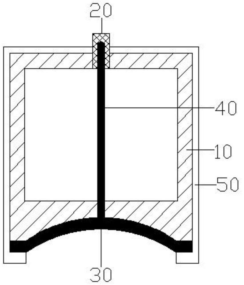
[0037] Such as figure 1 Shown is the self-focusing ultrasonic transducer in the embodiment of the present invention, which includes a support 10, a cross-linked polypropylene piezoelectric electret film 30, a shielding wire 40 and a silver film 50, and the upper end of the support 10 is provided with a connection Connector 20.

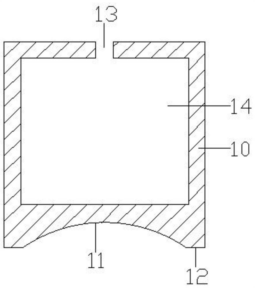
[0038] Such as figure 2 As shown, the bottom of the support member 10 is provided with a concave spherical surface 11 , and the circumference of the concave spherical surface 11 is provided with an annular plane 12 .

[0039] Such as figure 1 As shown, the upper and lower surfaces of the cross-linked polypropylene piezoelectric electret film 30 are pri...


PUM

PropertyMeasurementUnit
radiusaaaaaaaaaa
heightaaaaaaaaaa
radiusaaaaaaaaaa

Abstract

The invention discloses a self-focusing ultrasonic transducer, a floor mopping robot and an acoustic impedance calculating method. The self-focusing ultrasonic transducer comprises a supporting piece,a cross-linked polypropylene piezoelectric electret film, a shielded wire and a silver skin. A concave spherical surface is disposed at the bottom of the supporting piece. An annular flat surface isdisposed on the periphery of the concave spherical surface in a surrounding mode. A connecting joint is disposed at the upper end of the supporting piece. The upper surface and the lower surface of the cross-linked polypropylene piezoelectric electret film are each printed with conductive silver paste, and the cross-linked polypropylene piezoelectric electret film covers the interior of the concave spherical surface. One end of the shielded wire is connected with the edge of the lower surface of the cross-linked polypropylene piezoelectric electret film, and the other end of the shielded wireis connected with the connecting joint to serve as a positive electrode. The silver layer is plated on the surface of the supporting piece, and the upper surface of the cross-linked polypropylene piezoelectric electret film is connected with the connecting joint through the silver film to serve as a positive electrode. The self-focusing ultrasonic transducer can realize self-focusing of acoustic energy, recognize and detect acoustic resistance of reflectors, recognize different materials of the reflectors, and control the robot to be switched into different working modes according to the different materials.

Description

technical field [0001] The invention relates to the technical field of sweeping robots, in particular to a self-focusing ultrasonic transducer, a sweeping robot and an acoustic impedance calculation method. Background technique [0002] Sweeping robots are becoming more and more popular in society due to their efficient and intelligent cleaning methods. Sweeping robots generally use brush sweeping and vacuum methods to absorb ground debris into their own garbage storage boxes, thereby completing the function of ground cleaning. In addition, some sweeping robots are equipped with water tanks to complete the mopping function. When cleaning, if it encounters a carpet, it will change the walking path of the sweeping robot to avoid damage to the carpet. Therefore, it is necessary to detect floor materials such as carpets. [0003] At present, in the prior art, the carpet detection method of the sweeping robot is to judge whether there is a carpet according to the change of the...

Claims


Application Information

Patent Timeline
Patent Type & Authority Applications(China)
IPC IPC(8): B06B1/06B06B3/00G01N29/09A47L11/24A47L11/28A47L11/40
CPCA47L11/24A47L11/28A47L11/4011A47L11/4061A47L2201/04B06B1/0696B06B3/00G01N29/09
Inventor 赵仲杰李峰温任华张磊潘永东
Owner NONGTAIKE KUNSHAN TEATING TECH CO LTD
Learn More