Soft magnetic material cutting device
A cutting device, a technology for soft magnetic materials, applied in shearing devices, driving devices, feeding devices, etc., can solve the problem of inability to cut soft magnetic materials of different diameters
- Summary
- Abstract
- Description
- Claims
- Application Information
AI Technical Summary
Problems solved by technology
Method used
Image

Examples
specific Embodiment approach 1
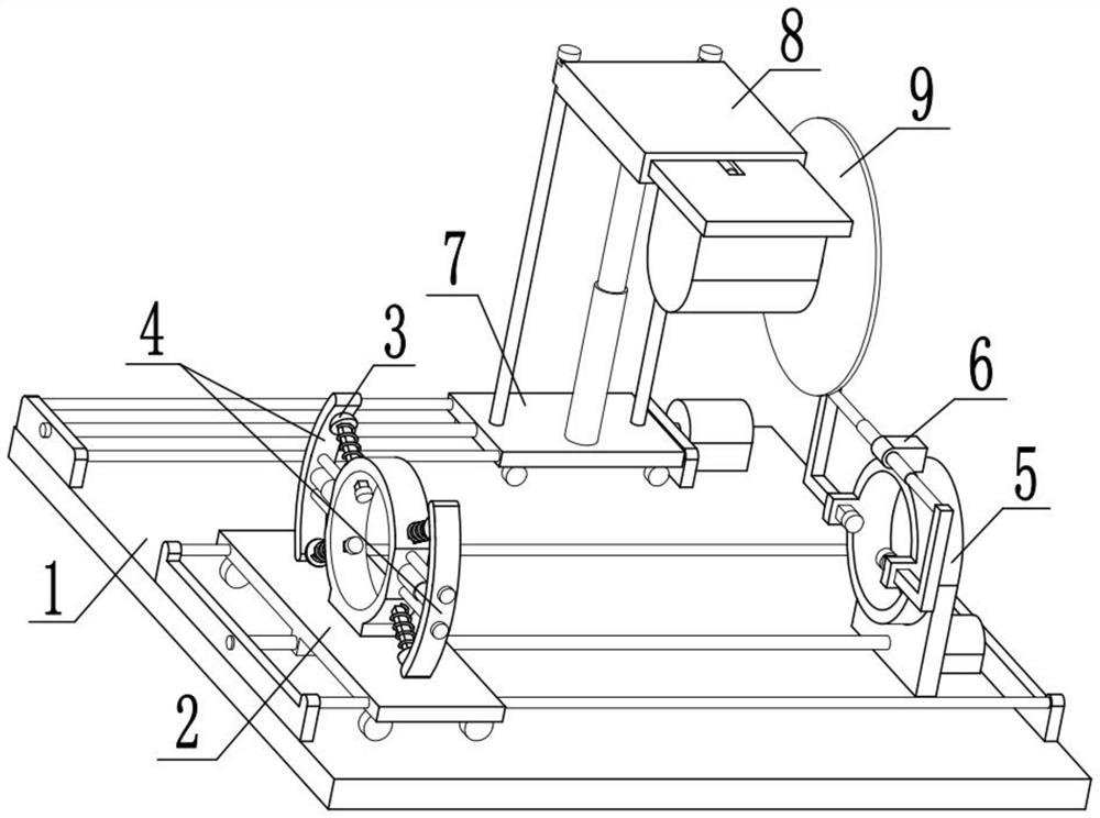
[0029] Combine below Figure 1-10 Describe this embodiment, the present invention relates to the field of soft magnetic material cutting technology, more specifically a soft magnetic material cutting device, including a cutting bearing desktop member 1, a sliding support device 2, a telescopic top column member 3, a telescopic extruding Device 4, abutting connection device 5, limit fixing device 6, mobile bearing panel 7, lifting sliding chamber device 8 and lifting cutting device 9, place the soft magnetic material in the fixed ring 2-2 and reach the abutting ring 5- 2, start two telescopic rods I4-4 and use four extrusion columns I3-2 to fix the material, and start two telescopic rods II6-2 to use two extrusion columns II6-4 to fix the other end of the material , start the motor II1-9 to adjust the position of the cutting piece 9-4, thereby changing the length of the cutting material, start the telescopic rod IV9-2 to drive the cutting piece 9-4 to slide backward, start the ...
specific Embodiment approach 2
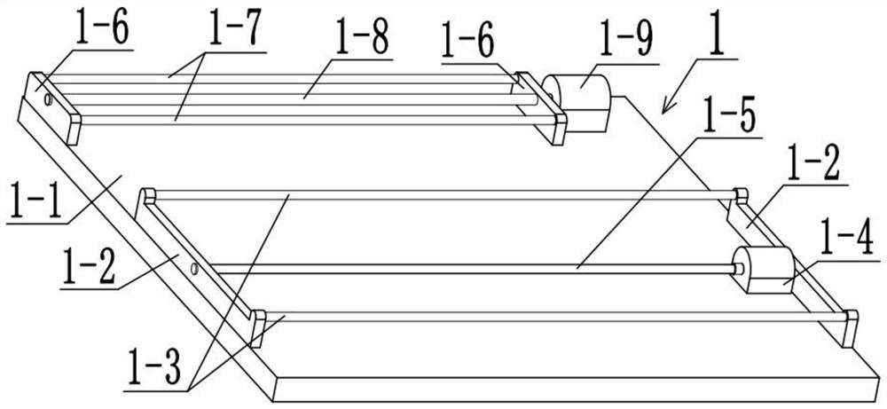
[0032] Combine below Figure 1-10 This embodiment will be described, and this embodiment will further explain the first embodiment. The cutting and bearing desktop member 1 includes a fixed bottom plate 1-1, a side ear plate I1-2, a limit sliding column I1-3, a motor I1-4, Lead screw I1-5, side ear plate II1-6, limit sliding column II1-7, lead screw II1-8 and motor II1-9, fixed bottom plate 1-1 plays the role of load-bearing connection, fixed bottom plate 1-1 The left and right ends of the rear are fixedly connected with side ear plates I1-2, the two side ear plates I1-2 can provide a fixed space for the two limit sliding posts I1-3, and the two side ear plates I1- 2 are fixedly connected with two limit sliding columns I1-3, and the two limit sliding columns I1-3 can provide a sliding space for the supporting convex plate 2-1, and limit it, and fix the bottom plate 1- 1 is fixedly connected with a motor I1-4, the motor I1-4 can drive the lead screw I1-5 to rotate, the output ...
specific Embodiment approach 3
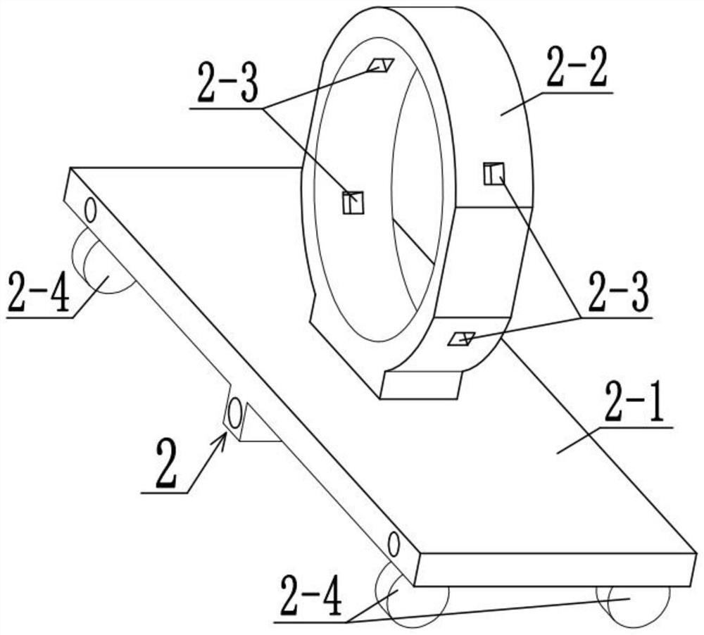
[0034] Combine below Figure 1-10 Describe this embodiment, this embodiment will further explain the second embodiment, the sliding support device 2 includes a support convex plate 2-1, a fixed ring 2-2, a square sliding port 2-3 and a roller I2-4 , the supporting convex plate 2-1 is slidably connected with two limit sliding posts I1-3 and threaded with the lead screw I1-5, the supporting convex plate 2-1 can provide a fixed space for the fixed ring 2-2 and Drive it to move, the supporting convex plate 2-1 is fixedly connected with the fixed ring 2-2, the fixed ring 2-2 can provide the space for the soft magnetic material to pass through, and the fixed ring 2-2 is provided with four square sliding openings 2-3, four square sliding openings 2-3 can provide sliding space for four square sliding columns 3-1, and four rollers I2-4 are fixedly connected to the bottom of the supporting convex plate 2-1, when the four rollers When I2-4 are all in contact with the fixed base plate 1-...
PUM
 Abstract
Description
Claims
Application Information
 - R&D Engineer
- R&D Manager
- IP Professional
- Industry Leading Data Capabilities
- Powerful AI technology
- Patent DNA Extraction
Browse by: Latest US Patents, China's latest patents, Technical Efficacy Thesaurus, Application Domain, Technology Topic.
© 2024 PatSnap. All rights reserved.Legal|Privacy policy|Modern Slavery Act Transparency Statement|Sitemap