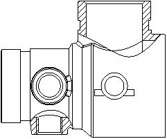
Welding ball valve test fixture and use method thereof
A technology for testing fixtures and ball valves, which can be used in mechanical valve testing, manufacturing tools, workpiece clamping devices, etc., and can solve problems such as time-consuming, laborious, cracking, and poor sealing
- Summary
- Abstract
- Description
- Claims
- Application Information
AI Technical Summary
Problems solved by technology
Method used
Image
Examples
Embodiment 1
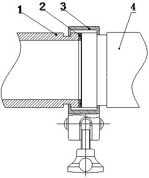
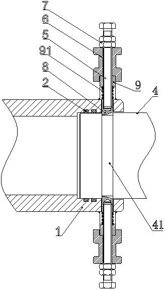
[0036] like Figure 1-2 As shown, at present, the welding joint 4 is connected to the test line. Generally, the welding joint 4 is docked with the chuck 1, and an O-ring 2 is arranged between the welding joint 4 and the chuck 1, and then the clamp is clamped by the clamp 3. The head 1 and the welding joint 4 are locked, considering the problems in the background technology, such as Figure 3-4 As shown, this embodiment proposes a welded ball valve test fixture, including a chuck 1, a stepped hole is opened inside the chuck 1, a welded joint 4 is inserted in the stepped hole, and a welded joint 4 is provided on the inner wall of the stepped hole to cooperate with the welded joint 4. The O-ring 2 plays a sealing role; the outer wall of the welding joint 4 is provided with a card slot 41, and the chuck 1 is provided with a slide hole communicating with the stepped hole, and a lock tongue 8 is slidably connected to the slide hole, and the lock tongue 8 cooperates with the card Co...
Embodiment 2
[0047] like Figure 5-6 As shown, on the basis of Embodiment 1, this embodiment proposes a welded ball valve test fixture, wherein the connector 5 is a bolt; the spring 91 seat 9 is also connected to the buckle 6, and the buckle 6 is provided with a through cavity. The bolt extends to the outside through the cavity; the bottom of the buckle 6 is provided with a groove 61, and the end of the seat 9 of the spring 91 is clamped in the groove 61.
[0048] The bolt is also threaded with a nut 7, the nut 7 is in contact with the end face of the seat 9 of the spring 91, and the height of the dead bolt 8 can be adjusted through the nut 7.
[0049] The present invention is designed with two different deadbolt 8 driving devices, which are ingenious in design and reasonable in structure. The designed wrench adopts the principle of leverage to save labor; the designed lifting buckle 6 is more stable when the limit is fixed; no matter what kind of driving It is very convenient to use, and...
PUM
 Abstract
Description
Claims
Application Information
 - R&D
- Intellectual Property
- Life Sciences
- Materials
- Tech Scout
- Unparalleled Data Quality
- Higher Quality Content
- 60% Fewer Hallucinations
Browse by: Latest US Patents, China's latest patents, Technical Efficacy Thesaurus, Application Domain, Technology Topic, Popular Technical Reports.
© 2025 PatSnap. All rights reserved.Legal|Privacy policy|Modern Slavery Act Transparency Statement|Sitemap|About US| Contact US: help@patsnap.com


