
Concrete stirring device for construction

A technology of mixing device and concrete, applied in cement mixing device, clay preparation device, unloading device, etc., can solve the problems of affecting construction progress, long mixing time and slowness, etc.

Inactive Publication Date: 2020-10-23
牛祥
View PDF0 Cites 4 Cited by
  • Summary
  • Abstract
  • Description
  • Claims
  • Application Information

AI Technical Summary

Problems solved by technology

There are two kinds of mixing methods: manual and mechanical. With the development of machinery, people now use machinery to mix concrete. However, the existing mechanical mixing devices add water directly from the top of the mixing tank, and the water comes from the upper layer. Entering and slowly penetrating into the lower layer, this process is relatively slow, resulting in too long mixing time, which will affect the subsequent construction progress

Method used


Image

  • Concrete stirring device for construction
  • Concrete stirring device for construction
  • Concrete stirring device for construction

Examples


Embodiment 1

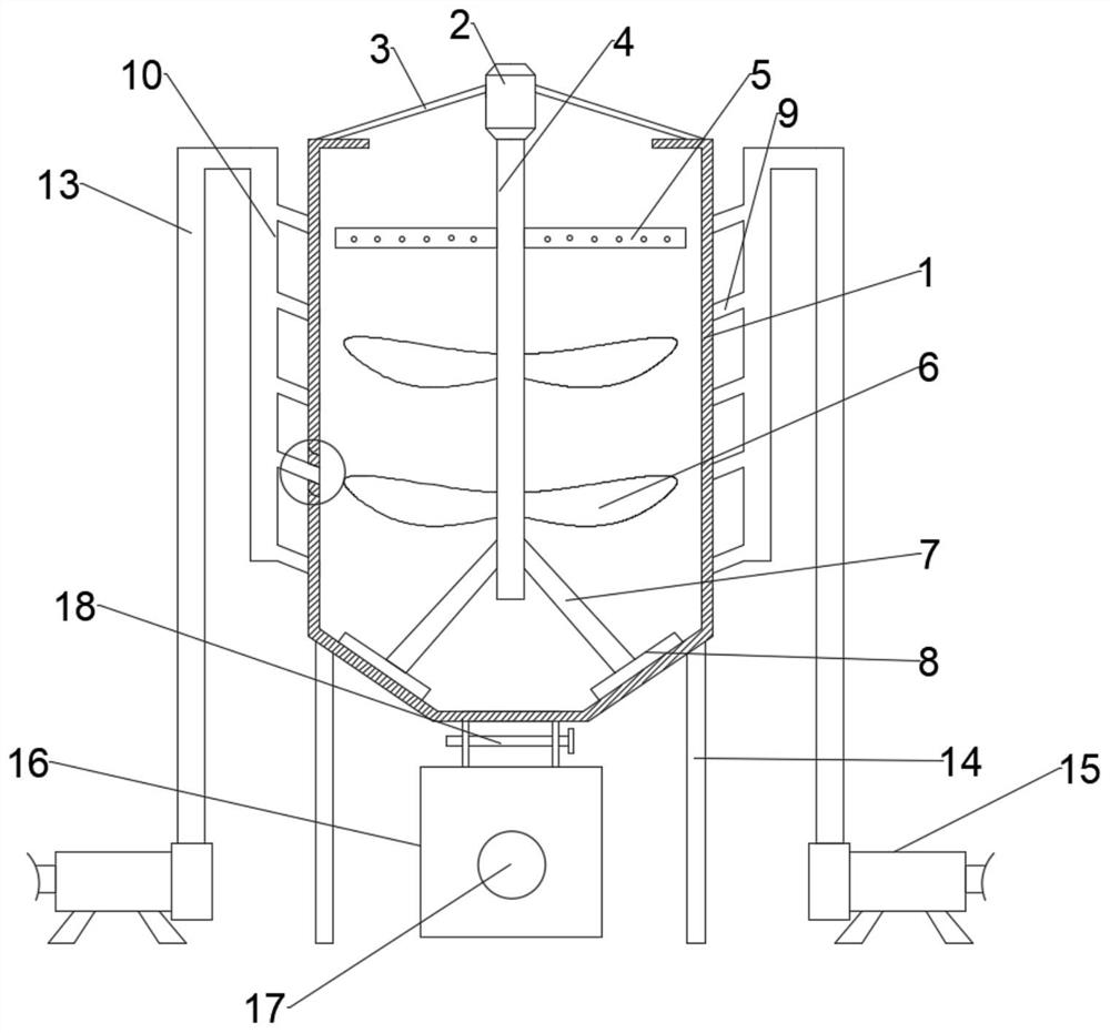
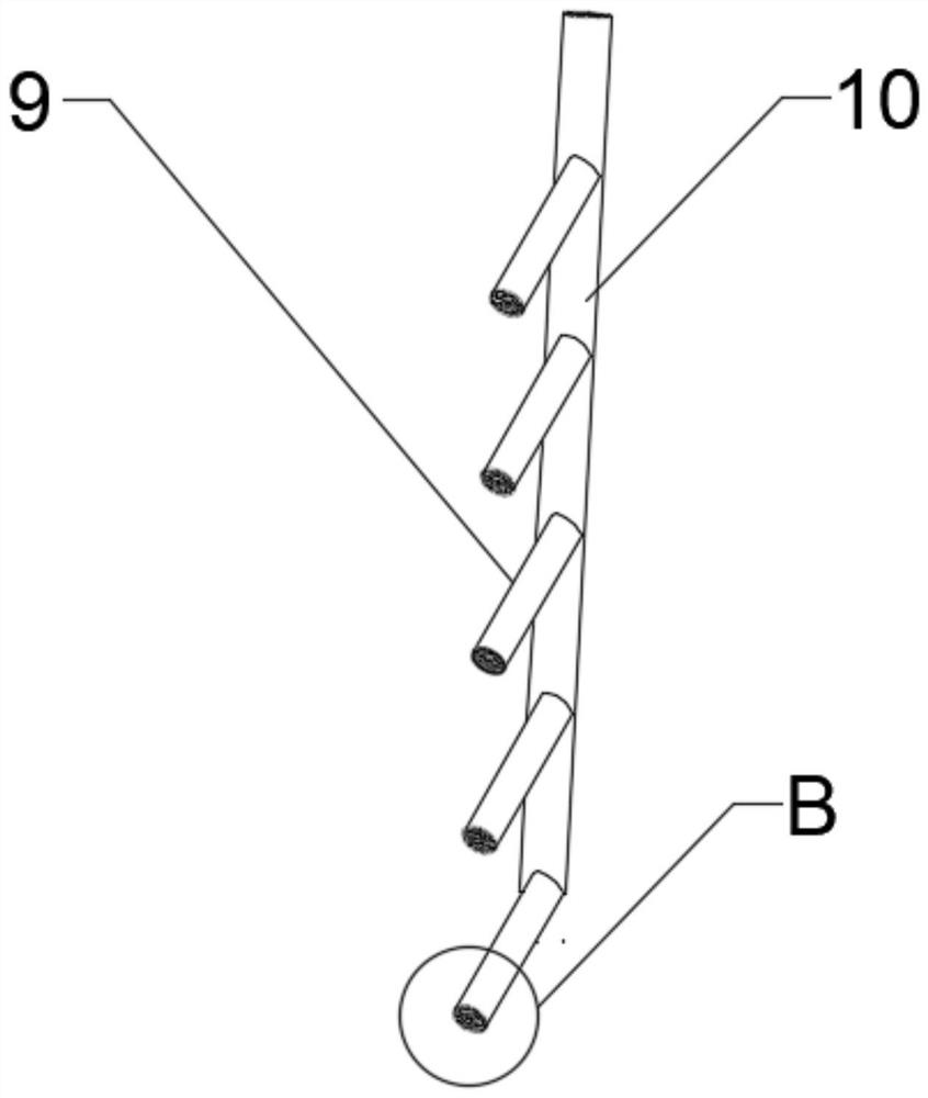
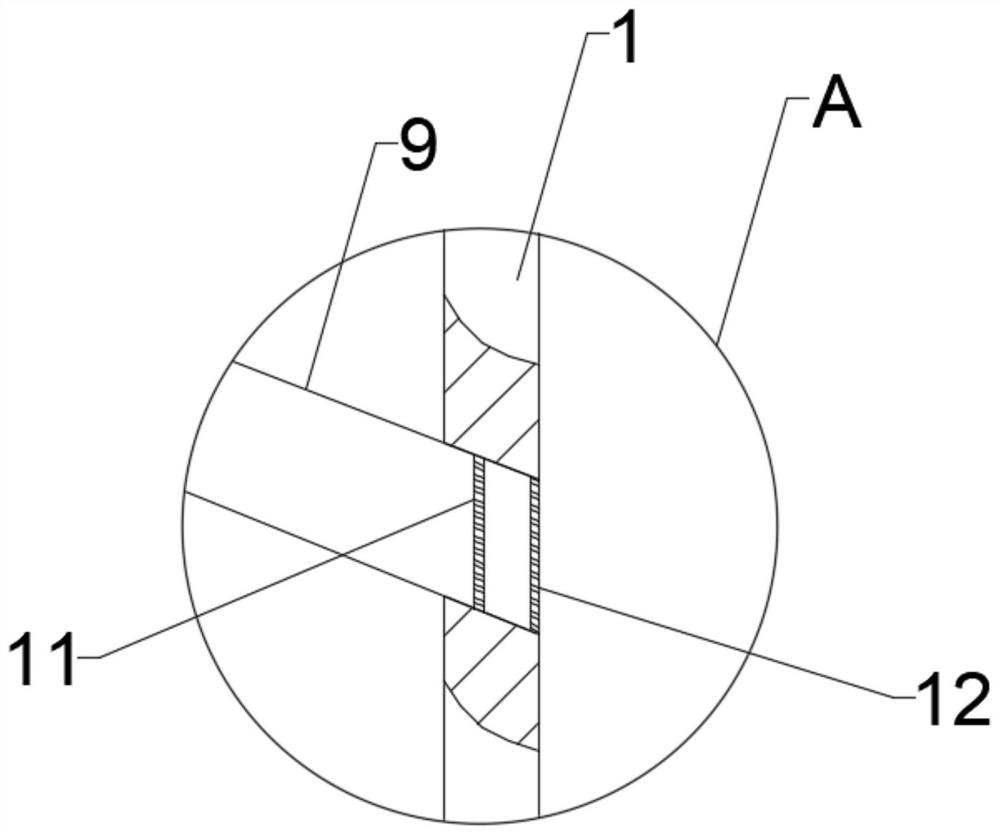
[0021] Combine Figure 1-4 , A concrete mixing device for construction, comprising a mixing tank 1 and a pillar 14, wherein the pillar 14 is fixed at the lower end of the mixing tank 1, and the pillar 14 is provided to support the mixing tank 1 to improve the stability of the mixing process. A plurality of first water pipes 9 are provided on both sides of the mixing tank 1, and one end of the plurality of first water pipes 9 on both sides penetrates the side wall of the mixing tank 1 and is connected to the inner wall of the mixing tank 1, and the other ends are connected To the second water pipe 10, a plurality of the first water pipes 9 are evenly distributed on both sides of the mixing tank 1 from top to bottom. The second water pipe 10 is connected to the booster water pump 15 through the third water pipe 13, and is The water pump 15, the third water pipe 13, the second water pipe 10, and the first water pipe 9 cooperate to inject water into the upper, middle and lower part...

Embodiment 2

[0028] Combine figure 1 , A concrete mixing device for construction, this embodiment further defines the device on the basis of the embodiment.

[0029] A delivery pump 16 is connected to the lower end of the discharge port, and a delivery pipe 17 is installed on the delivery pump 16.

[0030] Specifically, after the mixing is completed, the partition 18 is opened, and the concrete material flows into the delivery pump 16 from the discharge port, and is delivered to the construction site through the delivery pipeline 17.


PUM


Abstract

The invention discloses a concrete stirring device for construction. The concrete stirring device comprises a stirring tank body and supporting columns, wherein the supporting columns are fixed at thelower end of the stirring tank body, a plurality of first water pipes are arranged on two sides of the stirring tank body, one ends of the first water pipes on the two sides penetrate through the side walls of the stirring tank body and are connected with the inner walls of the stirring tank body, and the other ends of the first water pipes are connected to second water pipes; and the first waterpipes are uniformly distributed on the two sides of the stirring tank body from top to bottom, the second water pipes are connected to booster water pumps through third water pipes, and first and second sieve hole plates are fixed in the positions, connected to the inner wall ends of the stirring tank body, of the first water pipes. According to the concrete stirring device, the plurality of first water pipes are obliquely connected to the two sides of the stirring tank body, and water is simultaneously injected into the upper, middle and lower parts of the stirring tank body through the cooperation of the booster water pump, the third water pipes, the second water pipes and the first water pipes, so that the water is prevented from permeating slowly from top to bottom, the stirring timeis reduced, and the stirring efficiency is improved.

Description

Technical field [0001] The present invention relates to the field of construction technology, in particular to a concrete mixing device for construction. Background technique [0002] Concrete mixing is an operation method for mixing cement, lime, water and other materials and mixing them evenly. There are two mixing methods, manual and mechanical. With the development of machinery, people now mostly use machinery to stir the concrete. However, the existing mechanical stirring device adds water directly from the top of the mixing tank, and the water is added from the upper layer. Into the lower layer slowly, this process is relatively slow, resulting in too long mixing time, which will affect the subsequent construction progress. Summary of the invention [0003] The purpose of the present invention is to provide a concrete mixing device for construction to solve the problems raised in the background art. [0004] In order to achieve the above objectives, the present invention pro...

Claims


Application Information

Patent Timeline
IPC IPC(8): B28C5/16B28C7/12B28C7/16
CPCB28C5/16B28C7/12B28C7/126B28C7/163
Inventor 牛祥
Owner 牛祥
Learn More