
Display panel cutting device

A display panel and cutting device technology, applied in glass cutting devices, identification devices, glass manufacturing equipment, etc., can solve the problems of easy generation of cutting powder, large noise and vibration, deformation or damage of the cutting part of the parent display panel, etc.

Pending Publication Date: 2020-10-23
江苏亚威艾欧斯激光科技有限公司
View PDF6 Cites 0 Cited by
  • Summary
  • Abstract
  • Description
  • Claims
  • Application Information

AI Technical Summary

Problems solved by technology

[0005] In view of the above-mentioned shortcomings of the prior art, the purpose of the present invention is to provide a display panel cutting device, which is used to solve the problem that the display panel cutting device in the prior art is likely to cause deformation or damage to the cutting part of the mother display panel, which is not suitable for cutting. Technical problems such as flexible display panel, easy generation of cutting powder, special setting of cutting powder recovery device, and large noise and vibration that deteriorate the working environment

Method used


Image

  • Display panel cutting device
  • Display panel cutting device
  • Display panel cutting device

Examples


Embodiment Construction

[0036] Embodiments of the present invention are described below through specific examples, and those skilled in the art can easily understand other advantages and effects of the present invention from the content disclosed in this specification. The present invention can also be implemented or applied through other different specific implementation modes, and various modifications or changes can be made to the details in this specification based on different viewpoints and applications without departing from the spirit of the present invention.

[0037] In the description of the present invention, it should be noted that the terms "center", "upper", "lower", "left", "right", "vertical", "horizontal", "inner", "outer" etc. The indicated orientation or positional relationship is based on the orientation or positional relationship shown in the drawings, and is only for the convenience of describing the present invention and simplifying the description, rather than indicating or im...


PUM


Abstract

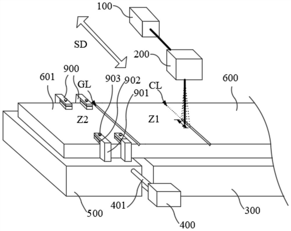
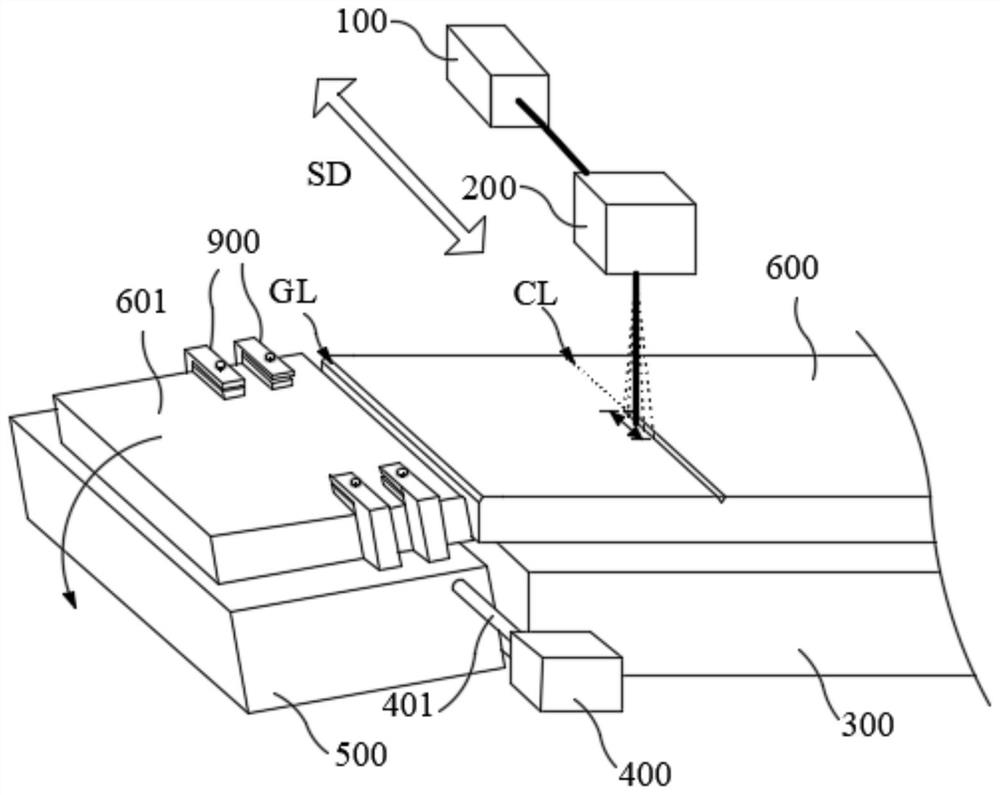
The invention provides a display panel cutting device which comprises a first bearing platform; a second bearing platform and the first bearing platform are arranged at an interval; a first driving unit is connected with the second bearing platform, and the first driving unit drives the second bearing platform to rotate in the direction of the side, away from the display panel, of the second bearing platform with a rotating shaft parallel to a cutting groove as the rotating center so as to provide bending force for the cutting groove; at least one pair of clamping units is arranged on the table top, close to one end of the first bearing platform, of the second bearing platform. By means of the display panel cutting device, noise and vibration generated in the display panel cutting processcan be minimized, the cutting part of the display panel is prevented from deforming or being damaged due to striking, and therefore the yield and productivity of the cutting process are improved, andthe situation that the quality of the display panel is reduced due to scattered cutting powder can be prevented.

Description

technical field [0001] The invention relates to the technical field of display panel cutting, in particular to a display panel cutting device. Background technique [0002] Display panels such as liquid crystal displays (LCDs), plasma display panels (PDPs) or organic light-emitting diodes (OLEDs) are used as display devices for electronic equipment such as TVs, screens, palmtop computers, and navigators. When making the above-mentioned display panels, generally through Separating large mother display panels (made up of multiple sub-panels arranged in a matrix) improves process productivity. [0003] In order to separate each sub-panel from the mother display panel, it is generally possible to use a grooving process (using a diamond cutter wheel or a laser beam to form a cutting groove at the boundary of the sub-panel), then turn over the mother display panel, and hit all the sub-panels with a striking rod. The above cutting grooves are used to make the cracks propagate alon...

Claims


Application Information

Patent Timeline
Patent Type & Authority Applications(China)
IPC IPC(8): C03B33/08G09F9/30G09F9/313G09F9/35
CPCC03B33/082G09F9/30G09F9/301G09F9/35G09F9/313
Inventor 朱鹏程凌步军袁明峰滕宇冯高俊赵有伟孙月飞吕金鹏冷志斌
Owner 江苏亚威艾欧斯激光科技有限公司
Learn More