Pipeline impacting resisting protection device

A protective device and pipeline technology, applied in the direction of pipe components, pipes/pipe joints/fittings, elastic shock absorbers, etc., can solve problems such as pipe deformation, weld cracking, local dynamic stress exceeding, etc.

Pending Publication Date: 2020-10-23
XIAN THERMAL POWER RES INST CO LTD
View PDF0 Cites 3 Cited by
  • Summary
  • Abstract
  • Description
  • Claims
  • Application Information

AI Technical Summary

Problems solved by technology

This method cannot effectively absorb the impact energy of the pipeline, and the impact energy will be transmitted in the form of waves in the piping system, resulting in a wider range of impact and stronger destructive consequences
According to Newton's third law, under the cons...

Method used


Image

  • Pipeline impacting resisting protection device
  • Pipeline impacting resisting protection device
  • Pipeline impacting resisting protection device

Examples


Embodiment Construction

[0020] The present invention is described in further detail below in conjunction with accompanying drawing:

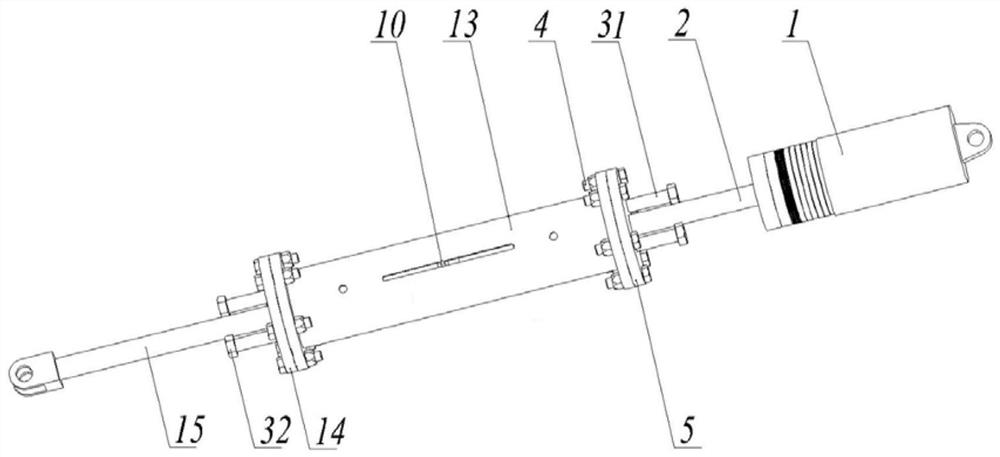
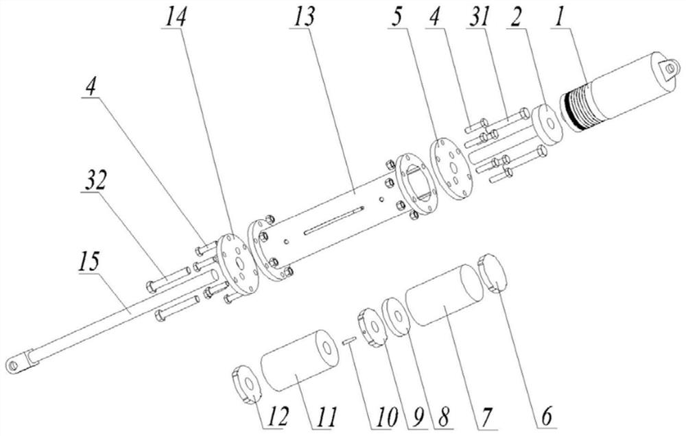
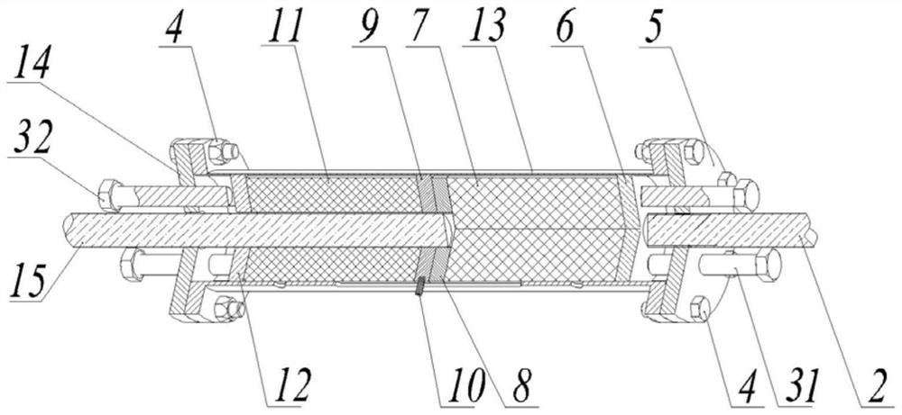
[0021] refer to Figure 1 to Figure 3 , the anti-pipeline impact protection device of the present invention includes a flange connecting rod 2, a hydraulic damper 1, an energy absorber lower connecting plate 5, an energy absorber lower pressure plate 6, a lower side energy absorbing block 7, and a locking plate 8. Action plate 9, upper side energy absorbing block 11, upper pressure plate 12 of energy absorber, shell of energy absorber 13, connecting rod 15 and upper connecting plate 14 of energy absorber; one end of flange connecting rod 2 and hydraulic damping The other end of the flange connecting rod 2 is connected with the lower connecting plate 5 of the energy absorber, the lower pressure plate 6 of the energy absorber, the lower energy absorbing block 7, the locking plate 8, the action plate 9, the upper side The energy absorbing block 11 and the upper pressure ...


PUM


Abstract

The invention discloses a pipeline impacting resisting protection device. A first annular guide groove, a second annular guide groove, a third annular guide groove are arranged on the inner wall of anenergy absorber shell. Guide bosses are arranged on the peripheral face of an energy absorber lower pressure plate, the peripheral face of an action disc and the peripheral face of an energy absorberupper pressure plate. The guide boss on the energy absorber lower pressure plate is embedded in the first guide groove, the guide boss on the action disc is embedded in the second guide groove, and the guide boss on the energy absorber lower pressure plate is embedded in the third guide groove. The end of a connecting rod sequentially penetrates through an energy absorber lower connecting plate,the energy absorber upper pressure plate, an upper energy absorption block, the action disc and a locking disc. The connecting rod is connected with the action disc and the locking disc, an energy absorber upper connecting plate is connected with the upper end of the energy absorber shell, and the energy absorber lower connecting plate is connected with the lower end of the energy absorber shell.The device has the advantages that active energy consumption is achieved, protection force is constant, and pipeline impacting dynamic stress can be reduced effectively.

Description

technical field [0001] The invention relates to a protection device, in particular to a protection device against pipeline impact. Background technique [0002] Pipeline is a transportation system that connects two or more equipment to transport media, and is widely used in thermal power plants, nuclear power plants, petrochemical and other energy industries. Due to the needs of operation, the opening and closing of the valves in the piping system are often adjusted during the production process, which will bring about a large impact and vibration of the pipeline, and when the operation is not correct, it will also cause the phenomenon of steam hammer and water hammer. The impact of pipeline vibration and the expansion wave and compression wave brought by steam hammer and water hammer are transmitted in the pipeline, and impact displacement will occur at elbows and valves. When the impact energy is large, it is easy to cause accidents such as pipeline cracking and medium lea...

Claims


Application Information

Patent Timeline
IPC IPC(8): F16L55/035F16F13/00F16F7/12
CPCF16F7/121F16F7/128F16F13/00F16F2222/12F16F2224/0208F16F2224/0225F16F2230/0023F16F2230/0047F16L55/035
Inventor 陈尚军王军民陈盛广康豫军武彦飞李楠林程肖军李亚亮杜小斌
Owner XIAN THERMAL POWER RES INST CO LTD
Why Eureka
Try Eureka