Eureka AIR delivers breakthrough ideas for toughest innovation challenges, trusted by R&D personnel around the world.

Thrust ball bearing optical interference linear oil film thickness detection method

A technology for thrust ball bearings and oil film thickness, which is applied in the field of testing and can solve problems such as inability to accurately reflect the state of oil film thickness

Active Publication Date: 2020-10-23
HANGZHOU DIANZI UNIV
View PDF6 Cites 0 Cited by
  • Summary
  • Abstract
  • Description
  • Claims
  • Application Information

AI Technical Summary

Problems solved by technology

[0005] The purpose of the present invention is to solve the problem that the existing optical interference film thickness measurement method based on the ball and disc cannot accurately reflect the oil film thickness state in the actual bearing, and to provide a thrust ball bearing light interference linear oil film thickness detection method, which can simulate the thrust ball bearing Complicated working conditions when placed vertically, and to detect the thickness of the oil film between the raceway and the roller at different positions, to conduct online observations of the grease supply at the entrance of the point contact area at different speeds and the evolution of the overall grease pool, and to monitor the After the test, the lubrication distribution form (grease whisker) in the bearing is measured and observed

Method used


Image

  • Thrust ball bearing optical interference linear oil film thickness detection method
  • Thrust ball bearing optical interference linear oil film thickness detection method
  • Thrust ball bearing optical interference linear oil film thickness detection method

Examples


Embodiment Construction

[0034] The present invention will be further described below in conjunction with accompanying drawing.

[0035] A thrust ball bearing optical interference linear oil film thickness detection method, specifically as follows:

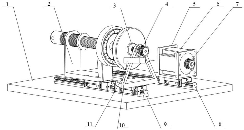
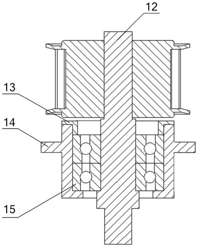
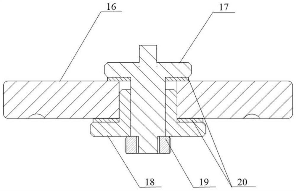
[0036] Step 1, such as figure 1 and 2 As shown, the transmission module support slide rail 9 set horizontally is fixed on the test bench base 1, and the transmission module support 11 and the transmission module support slide rail 9 form a sliding pair; The through hole and the adjustment groove provided by the transmission module support slide rail are connected with the nut to realize the transmission module bracket being fixed on the transmission module support slide rail; then, the transmission shaft 12 is supported on the bearing outer shell through the double row angular contact ball bearing 15 14; fix the bearing washer 13 and the bearing outer shell with screws to limit the axial position of the double row angular contact ball bearing; finally, ...


PUM


Abstract

The invention discloses a thrust ball bearing optical interference linear oil film thickness detection method, aiming at the problem that an existing optical interference film thickness measuring method based on a ball disc cannot accurately reflect the thickness of an oil film in a bearing. The thrust ball bearing optical interference linear oil film thickness detection method comprises the stepsof: after a gap between a steel ball and a retainer is filled with lubricating grease, attaching a thrust ball bearing retainer steel ball assembly to a steel thrust ball bearing ring, so that a glass thrust ball bearing ring and the thrust ball bearing retainer steel ball assembly bear loads; then, shooting oil film light interference images between the steel ball in the thrust ball bearing retainer steel ball assembly and a raceway of the glass thrust ball bearing ring in rotating and rotation-stopping states of the glass thrust ball bearing ring by means of a microscope high-speed camera sequentially, and observing the shape of a second-phase grease pool; and finally, taking down the thrust ball bearing retainer steel ball assembly and the steel thrust ball bearing ring, shooting the morphology of grease whiskers in the raceway of the steel thrust ball bearing ring to obtain a grease whisker angle mean value. The thrust ball bearing optical interference linear oil film thickness detection method can analyze the oil film state and a backflow mechanism of base oil during actual operation of a bearing.

Description

technical field [0001] The invention belongs to the technical field of testing and relates to detection of bearing oil film thickness, in particular to a method for detection of thrust ball bearing light interference linear oil film thickness. Background technique [0002] As one of the basic components in mechanical equipment, rolling bearings have many advantages such as small sliding friction coefficient, high degree of industrial standardization, compact structure, and easy start-up. They are widely used in industry, transportation, agriculture, home appliances, aerospace, and national defense. Applications in many fields have a major impact on the development of the global machinery industry 4.0. As the most strategic basic industry in our country, it is the object of our country's focus and research. On the basis of the past 60 years of development, my country's bearing industry has already possessed considerable independent development capabilities, strong technical ...

Claims


Application Information

Patent Timeline
IPC IPC(8): G01B11/06
CPCG01B11/0675
Inventor 吴参杨凯陈颖李兴林
Owner HANGZHOU DIANZI UNIV
Why Eureka
Eureka Blog
Learn More