Eureka AIR delivers breakthrough ideas for toughest innovation challenges, trusted by R&D personnel around the world.

Vibration type magnetic field detection device

A detection device and vibration technology, which is applied in the direction of the magnitude/direction of the magnetic field, can solve complex and high-cost problems, and achieve the effect of simple device, low cost and high sensitivity

Inactive Publication Date: 2020-10-23
西安柯莱特信息科技有限公司
View PDF0 Cites 0 Cited by
  • Summary
  • Abstract
  • Description
  • Claims
  • Application Information

AI Technical Summary

Problems solved by technology

Traditional magnetic field detection devices are complex and costly. Exploring magnetic field detection devices based on new principles will help further reduce the complexity and cost of detection devices

Method used


Image

  • Vibration type magnetic field detection device
  • Vibration type magnetic field detection device

Examples


Embodiment 1

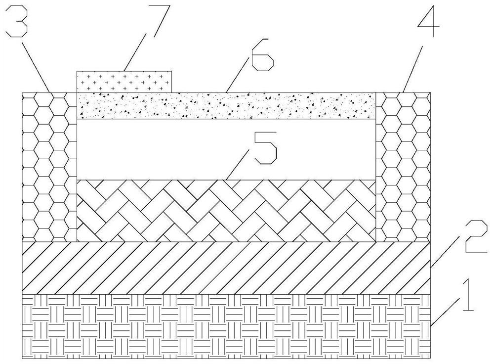
[0020] The invention provides a vibration type magnetic field detection device. Such as figure 1 As shown, the magnetic field detection device includes a vibration source 1 , an elastic layer 2 , a first fixing part 3 , a second fixing part 4 , a magnetostrictive part 5 , a vibration structure part 6 , and a piezoelectric material block 7 . The elastic layer 2 is placed on the vibration source 1 . The material of the elastic layer 2 is rubber, polyester material or acrylic material. Vibration source 1 is broadband. The magnetostrictive part 5 , the first fixing part 3 and the second fixing part 4 are placed on the elastic layer 2 . In practical applications, the first fixed part 3 and the second fixed part 4 can also go deep into the elastic layer 2, but the first fixed part 3 and the second fixed part 4 are not connected to the vibration source 1, so that the first fixed part 3 and the second fixed part 4 are not connected to the vibration source 1. The connection between...

Embodiment 2

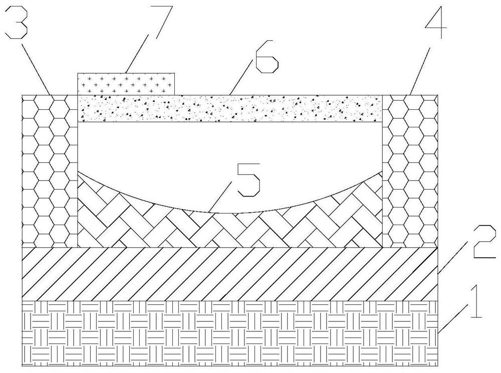
[0024] On the basis of Example 1, such as figure 2 As shown, the upper surface of the magnetostrictive part 5 is concave. In this way, more vibration space is left for the vibration structure part 5 . The following problems have been successfully solved: the magnetostrictive part 5 needs to be high so that the magnetostrictive part 5 can provide greater power to push the first fixed part 3 and the second fixed part 4 to separate, thereby increasing the vibration force in the vibrating structure part 6. Stress changes; however, when the magnetostrictive portion 5 is high, the vibrating structure portion 6 lacks a space for vibration. Because the vibration of the vibrating structure part 6 is strongest in the middle of the vibrating structure part 6, the upper surface of the magnetostrictive part 5 is set in a concave shape in this embodiment, which successfully solves the above-mentioned problem.

Embodiment 3

[0026] On the basis of the second embodiment, the vibrating structure part 6 is provided with through holes. The holes reduce the material consumption of the vibrating structure part 6. When a pulling force is applied at both ends of the vibrating structure part 6, more and more concentrated stresses are generated in the vibrating structure part 6, so that the natural vibration frequency of the vibrating structure part 6 changes more , which improves the sensitivity of magnetic field detection.

[0027] Furthermore, the holes are round or square for ease of preparation. On the contrary, if the holes are made into other special shapes, the requirements for the etching process are high.

[0028] Furthermore, the holes are strip-shaped. The direction of the bar is along the direction of the line connecting the first fixing part 3 and the second fixing part 4 . In this way, when tension is applied to both ends of the vibrating structure part 6, the distribution of the stress is...


PUM


Abstract

The invention relates to the field of magnetic field detection, and particularly provides a vibration type magnetic field detection device. The two ends of a magnetostriction part are fixedly connected to the bottom of a first fixing part and the bottom of a second fixing part respectively; the two ends of a vibration structure part are fixedly connected to the top of the first fixing part and thetop of the second fixing part respectively; and a piezoelectric material block is arranged at the position, close to the first fixing part, of the top of the vibration structure part and connected with an external circuit. During application, under the action of a to-be-measured magnetic field, the magnetostriction part extends, the stress in the vibration structure part is increased, and then the natural vibration frequency of the vibration structure part is changed; through the change of the natural vibration frequency, magnetic field measurement is realized; the device is simple, is low incost, is high in sensitivity, and has an important application value in the field of magnetic field detection.

Description

technical field [0001] The invention relates to the field of magnetic field detection, in particular to a vibration type magnetic field detection device. Background technique [0002] Traditional magnetic field detection is mostly based on Hall effect, magnetoresistance effect, fluxgate effect and tunnel effect. Traditional magnetic field detection devices are complex and costly. Exploring magnetic field detection devices based on new principles will help further reduce the complexity and cost of detection devices. Contents of the invention [0003] In order to solve the above problems, the present invention provides a vibrating magnetic field detection device, including: a vibration source, an elastic layer, a first fixed part, a second fixed part, a magnetostrictive part, a vibrating structure part, a piezoelectric material block; The layer is placed on the vibration source, the magnetostrictive part, the first fixed part and the second fixed part are placed on the elas...

Claims


Application Information

Patent Timeline
Patent Type & Authority Applications(China)
IPC IPC(8): G01R33/02
CPCG01R33/02
Inventor 不公告发明人
Owner 西安柯莱特信息科技有限公司
Why Eureka
Eureka Blog
Learn More