High-sensitivity vibration type magnetic field detection device

A detection device, vibrating technology, applied in the direction of the size/direction of the magnetic field, which can solve the problems of complexity and high cost

Inactive Publication Date: 2020-10-23
西安柯莱特信息科技有限公司
View PDF0 Cites 0 Cited by
  • Summary
  • Abstract
  • Description
  • Claims
  • Application Information

AI Technical Summary

Problems solved by technology

Traditional magnetic field detection devices are complex and costly. Exploring magnetic field detectio

Method used


Image

  • High-sensitivity vibration type magnetic field detection device
  • High-sensitivity vibration type magnetic field detection device
  • High-sensitivity vibration type magnetic field detection device

Examples


Embodiment 1

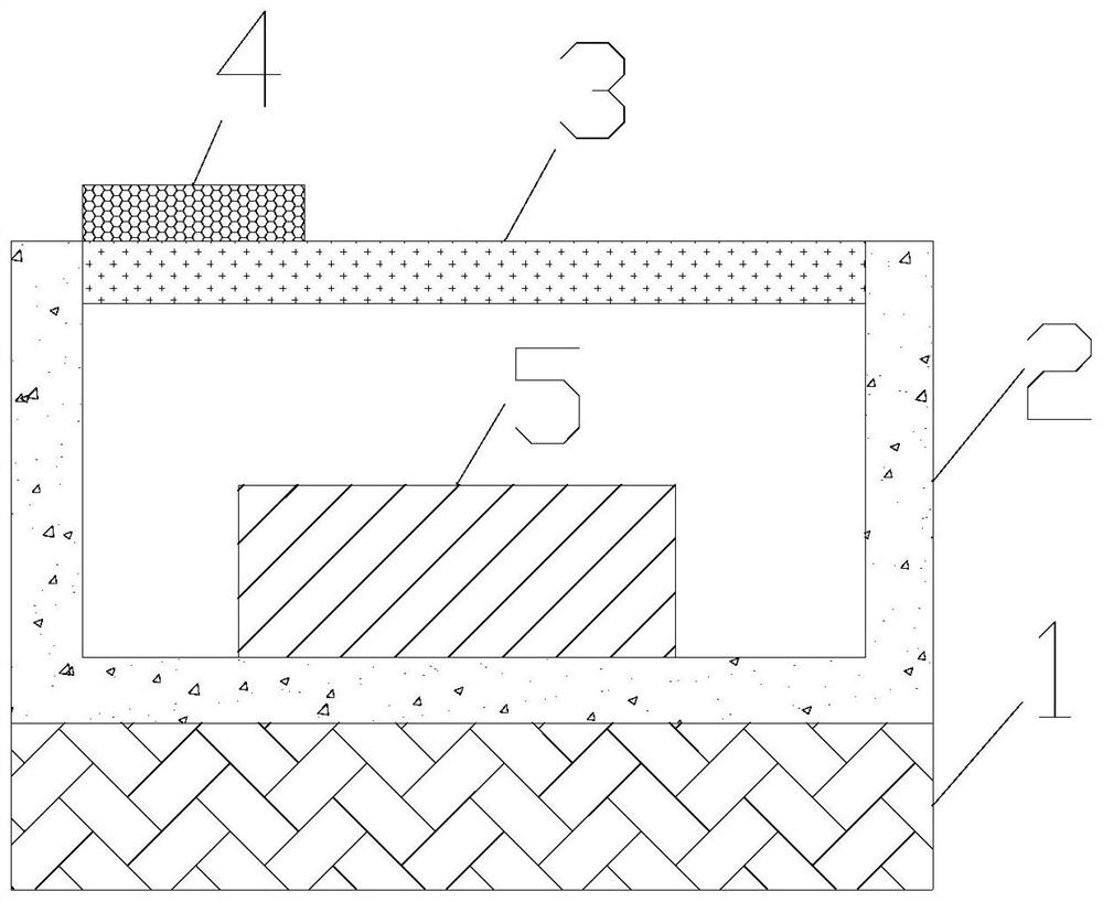
[0021] The invention provides a high-sensitivity vibration type magnetic field detection device. Such as figure 1 As shown, the magnetic field detection device includes a vibration source 1 , a wall 2 , a vibration structure part 3 , a piezoelectric material block 4 , and a magnetostrictive block 5 . The device wall 2 and the vibrating structure part 3 are fixedly connected, and the device wall 2 and the vibrating structure part 3 enclose a closed cavity. The material of the vibrating structure part 3 is aluminum alloy, silicon, semiconductor material, diamond. The bottom of the wall 2 is placed on the vibration source 1, and the vibration source 1 is broadband and provides vibration with a certain frequency range. The piezoelectric material block 4 is placed on the edge of the vibrating structure part 3 , and the piezoelectric material block 4 is connected to an external circuit for monitoring the vibration of the vibrating structure part 3 . The piezoelectric material blo...

Embodiment 2

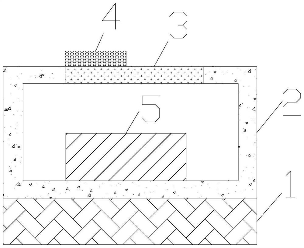
[0028] On the basis of Example 1, such as figure 2 As shown, the cavity is a cuboid. The area of ​​the vibration structure part 3 is smaller than the area of ​​the top surface of the cuboid. That is to say, compared with the vibration structure part 3 on the top surface of the cuboid, the size of the vibration structure part 3 is reduced in this embodiment. In this way, the size of the cavity can be set large, but the size of the vibrating structure part 3 is still small. In this way, the volume of the magnetostrictive block 5 in the cavity can be increased a lot, and these volume increases are reflected in the deformation of the small-sized vibrating structure part 3 . In this way, the stress in the vibrating structure part 3 is changed more, the natural frequency of the vibrating structure part 3 is changed more, and the sensitivity of magnetic field detection is improved.

Embodiment 3

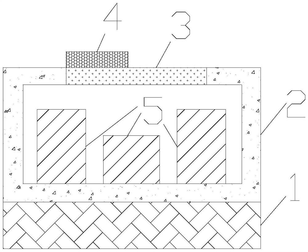
[0030] On the basis of Example 2, such as image 3 As shown, the number of magnetostrictive blocks is more than one. The characteristic directions of the magnetostrictive blocks 5 are different. Under the action of magnetic fields in different directions, different magnetostrictive blocks 5 can all be elongated, so that magnetic fields in different directions can be detected. In addition, the volume in the cavity is also fully utilized to place more magnetostrictive blocks 5 . Under the action of the magnetic field to be measured, the pressure in the cavity changes more, which improves the sensitivity of magnetic field detection.

[0031] Further, as image 3 As shown, in the middle of the cavity, the height of the magnetostrictive block 5 is smaller than the height of the magnetostrictive block 5 at the edge of the cavity. The vibrating structure part 3 is arranged at the center of the top surface of the cuboid. In this way, a space for vibration is reserved for the vibra...


PUM


Abstract

The invention provides a high-sensitivity vibration type magnetic field detection device. A closed cavity is defined by a device wall and a vibration structure part, the bottom of the device wall is arranged on a vibration source, the vibration source is broadband, a piezoelectric material block is arranged at the edge part of the vibration structure part, the piezoelectric material block is connected with an external circuit, a magnetostriction block and fluid are arranged in the cavity, and the magnetostriction block is not in contact with the vibration structure part. During application, under the action of a to-be-detected magnetic field, the magnetostriction block extends, so that the size of the magnetostriction block is increased, and the pressure in the cavity is increased, the stress in the vibration structure part is changed, and the natural vibration frequency of the vibration structure part is changed; the magnetic field detection is realized by measuring the movement of the natural vibration frequency; and the device is simple, low in cost and high in magnetic field detection sensitivity.

Description

technical field [0001] The invention relates to the field of magnetic field detection, in particular to a highly sensitive vibration type magnetic field detection device. Background technique [0002] Magnetic fields have important applications in production and life. Magnetic field detection is an important technology. Traditional magnetic field detection is mostly based on Hall effect, magnetoresistance effect, fluxgate effect and tunnel effect. Traditional magnetic field detection devices are complex and costly. Exploring magnetic field detection devices based on new principles will help further reduce the complexity and cost of detection devices. Contents of the invention [0003] In order to solve the above problems, the present invention provides a highly sensitive vibrating magnetic field detection device, comprising: a vibration source, a wall, a vibration structure, a piezoelectric material block, and a magnetostrictive block; the wall and the vibration structur...

Claims


Application Information

Patent Timeline
IPC IPC(8): G01R33/02
CPCG01R33/02
Inventor 不公告发明人
Owner 西安柯莱特信息科技有限公司
Why Eureka
Try Eureka