Eureka AIR delivers breakthrough ideas for toughest innovation challenges, trusted by R&D personnel around the world.

Wide-range magnetic field detection device

A detection device and wide-range technology, which is applied in the direction of the size/direction of the magnetic field, can solve the problems of narrow magnetic field detection range, complex device, high cost, etc., and achieve the effect of wide detection range

Inactive Publication Date: 2020-10-30
西安柯莱特信息科技有限公司
View PDF0 Cites 0 Cited by
  • Summary
  • Abstract
  • Description
  • Claims
  • Application Information

AI Technical Summary

Problems solved by technology

Traditional magnetic field detection devices have narrow magnetic field detection range, complex devices, and high cost. Exploring magnetic field detection devices based on new principles will help to further expand the range of magnetic field detection and reduce the system complexity and cost of magnetic field detection devices.

Method used


Image

  • Wide-range magnetic field detection device
  • Wide-range magnetic field detection device

Examples


Embodiment 1

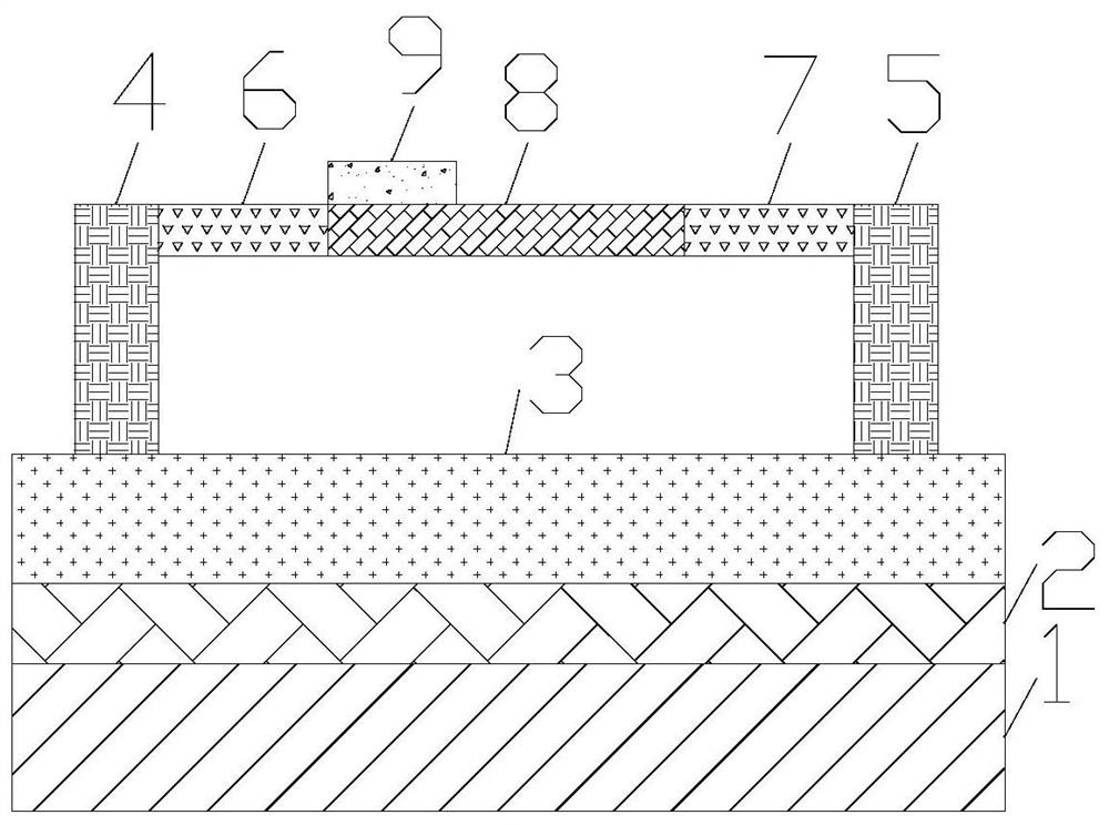
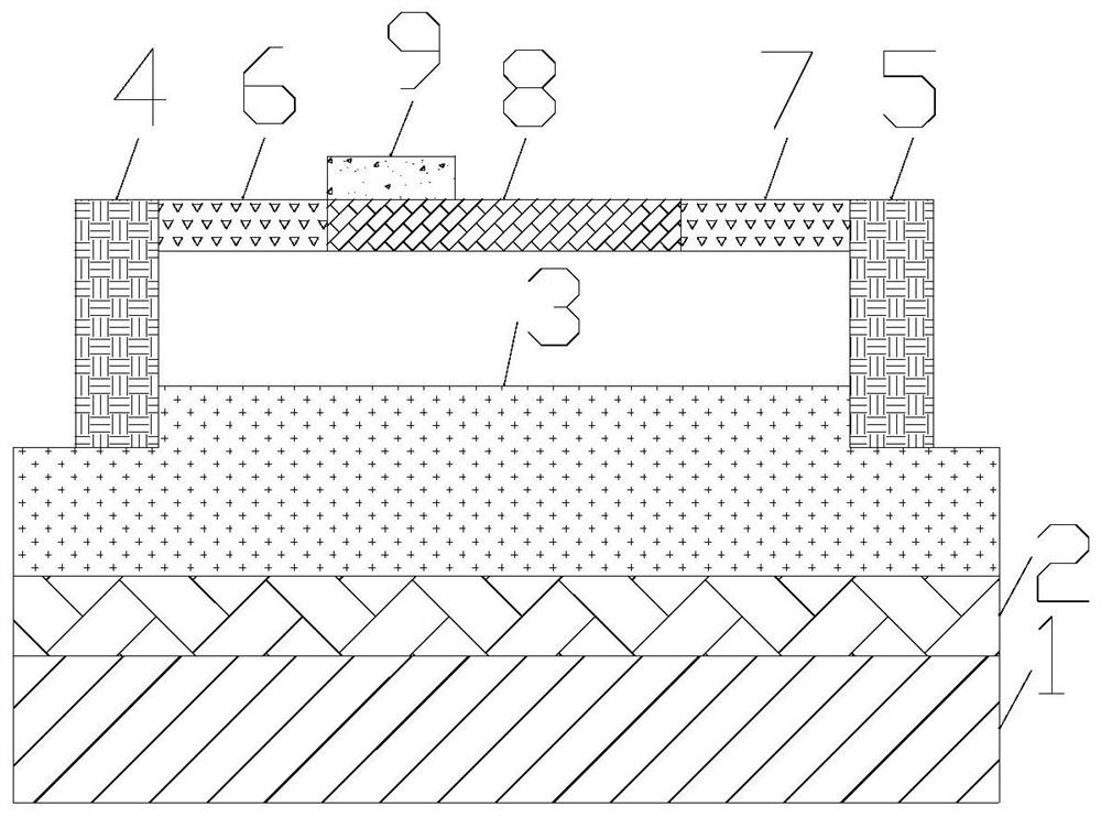
[0020] The invention provides a wide range magnetic field detection device. Such as figure 1 As shown, the magnetic field detection device includes a vibration source 1, an elastic layer 2, a magnetostrictive layer 3, a first fixed part 4, a second fixed part 5, a first connecting part 6, a second connecting part 7, and a vibration structure part 8 , Piezoelectric material block 9 . The elastic layer 2 is placed on the vibration source 1 . The vibration source 1 is broadband and can provide mechanical vibration in a certain frequency range. The material of the elastic layer 2 is rubber, polyester material or acrylic material. The magnetostrictive layer 3 is placed on the elastic layer 2 . Both ends of the vibration structure part 8 are fixedly connected to one end of the first connection part 6 and the second connection part 7 respectively, and the material of the vibration structure part 8 is aluminum alloy, silicon, semiconductor material, diamond. The other ends of the...

Embodiment 2

[0023] On the basis of Embodiment 1, screws are also included, and the screws are used to control the connection angles of the first connecting part 6 and the second connecting part 7 with the first fixing part 4 and the second fixing part 5 respectively. One screw passes through the connecting portion of the first connecting portion 6 and the first fixing portion 4 , and the other screw passes through the connecting portion of the second connecting portion 7 and the second fixing portion 5 . By tightening the screws, the relative angle between the first connecting portion 6 and the first fixing portion 4 and the relative angle between the second connecting portion 7 and the second fixing portion 5 are fixed. When the above angle is changed, the vibrating structure part 8 is elongated or compressed, thereby changing the stress in the vibrating structure part 8 and changing the natural frequency of vibration in the vibrating structure part 8 . The method for adjusting the inter...

Embodiment 3

[0025] On the basis of Embodiment 1, it also includes a force application part, which connects the first connection part 6 or the second connection part 7 to apply an external force in a direction perpendicular to the first connection part 6 or the second connection part 7 . through the figure 1 The external force is applied in the vertical direction, so that the first connecting part 6 or the second connecting part 7 is tilted, thereby stretching the vibrating structure part 8, thereby changing the stress in the vibrating structure part 8, thereby changing the force in the vibrating structure part 8 natural frequency of vibration. In this embodiment, the method for adjusting the internal stress of the vibrating structure part 8 is simple and easy to control.


PUM


Abstract

The invention provides a wide-range magnetic field detection device, which is characterized in that the two ends of a vibration structure part are fixedly connected with one end of a first connectingpart and one end of a second connecting part respectively; the other end of the first connecting part and the other end of the second connecting part are hinged to the top of a first fixing part and the top of a second fixing part respectively; the bottom of the first fixing part and the bottom of the second fixing part are fixedly connected with a magnetostriction layer; and a piezoelectric material block is arranged on the edge of the top face of the vibration structure part and connected with an external circuit. According to the invention, during application, under the action of a to-be-detected magnetic field, a magnetostriction layer extends to increase the stress in a vibration structure part, so that the natural vibration frequency of the vibration structure part is changed, and magnetic field detection is realized by measuring the change of the natural vibration frequency; and different stresses are applied in the vibration structure part in advance, and then the natural vibration frequency of the magnetic field to the vibration structure part is detected, so that the method has the advantage of wide detection range, and has important application value in the field of magnetic field detection.

Description

technical field [0001] The invention relates to the field of magnetic field detection, in particular to a wide-range magnetic field detection device. Background technique [0002] Traditional magnetic field detection is mostly based on Hall effect, magnetoresistance effect, fluxgate effect and tunnel effect. Traditional magnetic field detection devices have narrow magnetic field detection range, complex devices, and high cost. Exploring magnetic field detection devices based on new principles will help to further expand the range of magnetic field detection and reduce the system complexity and cost of magnetic field detection devices. Contents of the invention [0003] In order to solve the above problems, the present invention provides a wide-range magnetic field detection device, including: a vibration source, an elastic layer, a magnetostrictive layer, a first fixing part, a second fixing part, a first connecting part, a second connecting part, The vibration structure ...

Claims


Application Information

Patent Timeline
Patent Type & Authority Applications(China)
IPC IPC(8): G01R33/02
CPCG01R33/02
Inventor 不公告发明人
Owner 西安柯莱特信息科技有限公司
Why Eureka
Eureka Blog
Learn More