High-linearity attenuator

An attenuator, high linearity technology, applied in the direction of impedance network, digital technology network, electrical components, etc., can solve the problems of low precision, unsuitable for high power input, low linearity of attenuator, etc.

Active Publication Date: 2020-10-23
ZHEJIANG UNIV
View PDF8 Cites 2 Cited by
  • Summary
  • Abstract
  • Description
  • Claims
  • Application Information

AI Technical Summary

Problems solved by technology

[0007] In view of the above-mentioned shortcomings of the prior art, the purpose of the present invention is to provide a high linear attenuator

Method used


Image

  • High-linearity attenuator
  • High-linearity attenuator
  • High-linearity attenuator

Examples


Embodiment 1

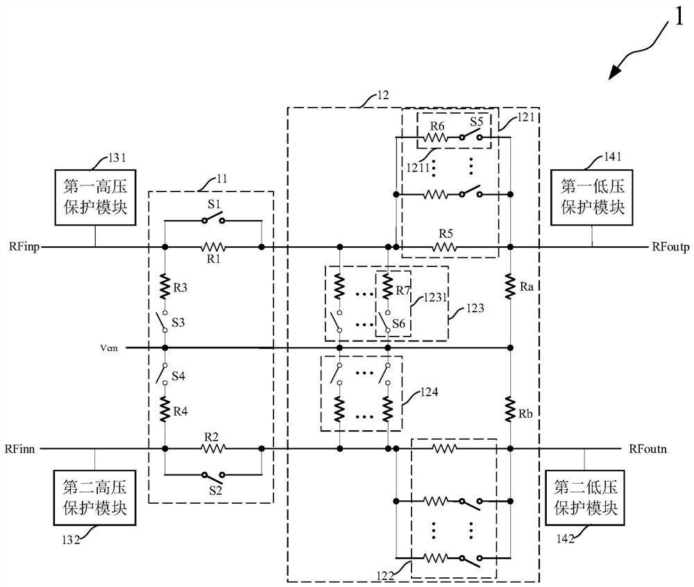
[0059] Such as figure 1 As shown, the present embodiment provides a high linearity attenuator 1, and the high linearity attenuator 1 includes:

[0060] Coarse attenuation module 11, fine attenuation module 12, high voltage protection module and low voltage protection module.

[0061] Such as figure 1 As shown, the coarse attenuation module 11 receives an input differential signal (positive phase input signal RFinp, negative phase input signal RFinn) and a common mode voltage Vcm, and performs rough adjustment of attenuation on the input differential signal.

[0062] Specifically, the coarse attenuation module 11 includes at least one stage of coarse attenuation unit. In this embodiment, the first stage of coarse attenuation unit is taken as an example, and the coarse attenuation unit provides 6dB attenuation. The coarse attenuation unit includes a first resistor R1 , a second resistor R2 , a third resistor R3 , a fourth resistor R4 , a first switch S1 , a second switch S2 , ...

Embodiment 2

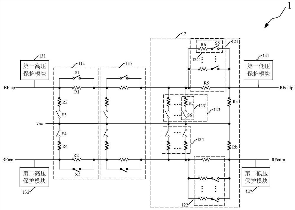
[0093] Such as image 3 As shown, this embodiment provides a high linearity attenuator, the difference from Embodiment 1 is that the coarse adjustment attenuation module 11 of the high linearity attenuator 1 includes two cascaded coarse adjustment attenuation units .

[0094] Specifically, the first coarse attenuation unit 11a receives an input signal, the second coarse attenuation unit 11b is connected to the output end of the first coarse attenuation unit 11a, and the fine attenuation module 12 is connected to the second coarse The output end of the attenuation unit 11b is cascaded in sequence. As an example, the first coarse attenuation unit 11a and the second coarse attenuation unit 11b have the same equivalent load impedance, and both provide an attenuation of 6dB.

[0095] The structure and principle of the first coarse attenuation unit 11a and the second coarse attenuation unit 11b are the same, and the structure and principle of the coarse attenuation unit and the fi...


PUM

PropertyMeasurementUnit
Resistanceaaaaaaaaaa

Abstract

The invention provides a high-linearity attenuator. The high-linearity attenuator comprises a coarse adjustment attenuation module, a fine adjustment attenuation module, a high-voltage protection module and a low-voltage protection module, the coarse adjustment attenuation module performs coarse adjustment of attenuation on the input differential signal and comprises at least one stage of coarse adjustment attenuation unit, and the coarse adjustment attenuation units are sequentially cascaded and have equal equivalent load impedance; the fine adjustment attenuation module performs attenuationfine adjustment on the signal output by the coarse adjustment attenuation module; the high-voltage protection module and the low-voltage protection module are connected to the input end and the outputend respectively; the coarse adjustment attenuation module and the fine adjustment attenuation module comprise high-linearity switches and resistors, attenuation adjustment is achieved based on on-off of the switches, and the working states of the switches comprise a high-voltage-withstanding partition state and an on-state of a low-on-resistance; and the resistor in the coarse adjustment attenuation module is a metal resistor. The high-linearity attenuator has the advantages of being high in precision, easy to expand the attenuation range, high in linearity, large in bandwidth, high in powerendurance capacity and the like.

Description

technical field [0001] The invention relates to the field of integrated circuit design, in particular to a high linearity attenuator. Background technique [0002] The attenuator is applied to the front end of the receiver to attenuate the excessive signal and avoid the saturation of the subsequent circuit, so that the receiver has a larger dynamic range, which requires the attenuator to have stronger power tolerance than the subsequent circuit ; In addition, the attenuator cannot introduce too much noise, otherwise it will affect the sensitivity of the receiver; moreover, the attenuator needs to have a gain adjustable function, so that the receiver can have the maximum output signal-to-noise ratio for different signal amplitudes. To sum up, the attenuator should have the ability of high linearity, low noise, good matching, and high-power input tolerance. [0003] At present, there are many receiver circuits such as low noise amplifiers, mixers, ADCs, etc., which are often ...

Claims


Application Information

Patent Timeline
IPC IPC(8): H03H17/00
CPCH03H17/00
Inventor 刘家瑞郁发新
Owner ZHEJIANG UNIV
Why Eureka
Try Eureka