
Farm wastewater treatment device

A technology for wastewater treatment and farms, which is applied in animal husbandry wastewater treatment, water/sewage treatment, light water/sewage treatment, etc. It can solve the problems of reducing wastewater treatment efficiency, reducing the service life of treatment devices, and affecting the surrounding environment of farms, etc.

Inactive Publication Date: 2020-10-27
庞俊平
View PDF0 Cites 1 Cited by
  • Summary
  • Abstract
  • Description
  • Claims
  • Application Information

AI Technical Summary

Problems solved by technology

[0003] When the farm cleans the breeding house, it will produce a large amount of wastewater, which will directly enter a wastewater reservoir. When the weather is hot, the surrounding area of ​​the wastewater reservoir will emit a disgusting smell, which will affect the surrounding environment of the farm. The existing wastewater treatment device is inconvenient to separate the solid and liquid in the wastewater, which reduces the efficiency of wastewater treatment and reduces the service life of the treatment device. Therefore, a wastewater treatment device for farms is needed

Method used


Image

  • Farm wastewater treatment device
  • Farm wastewater treatment device
  • Farm wastewater treatment device

Examples


Embodiment 1

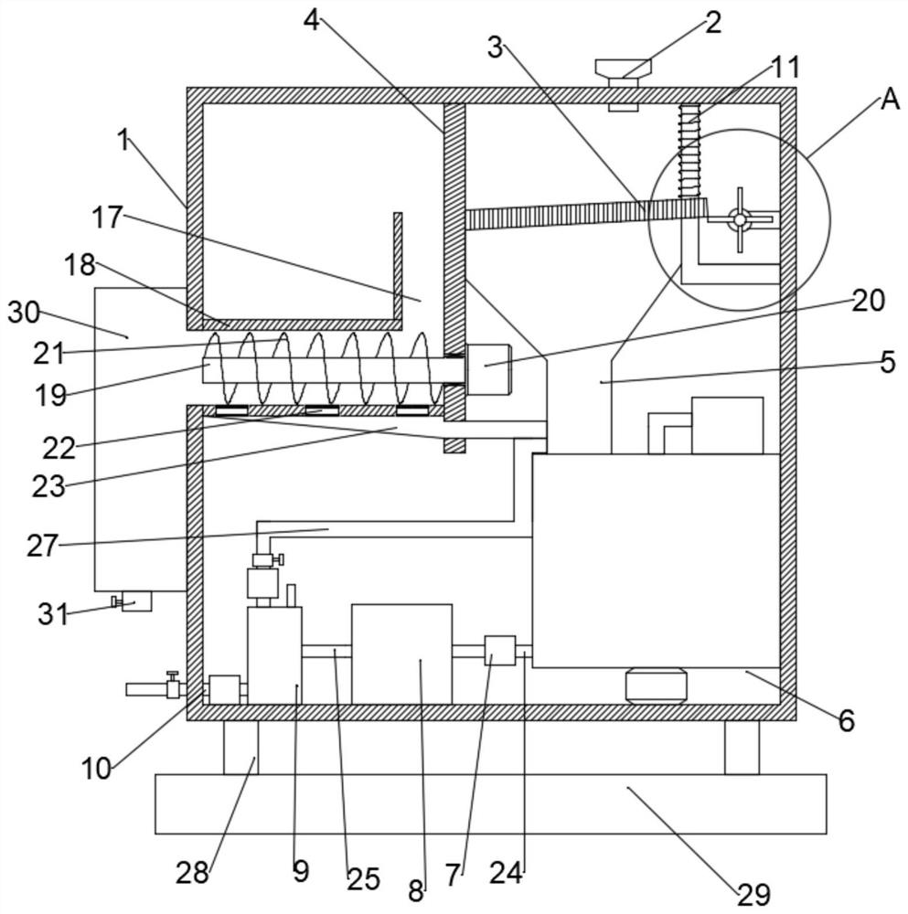
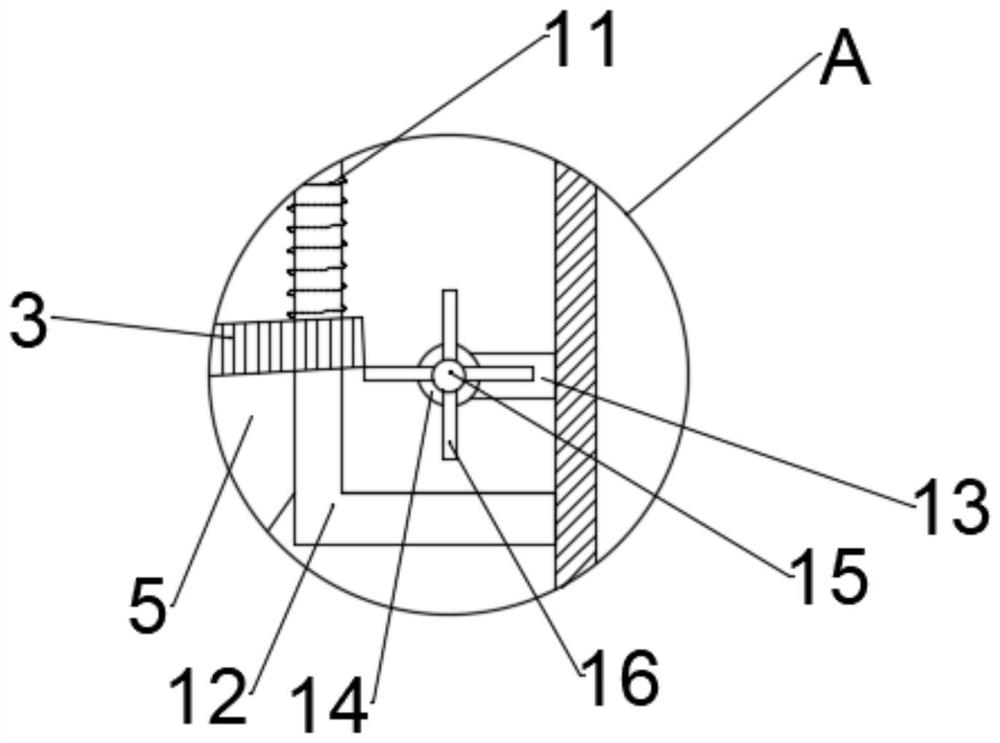
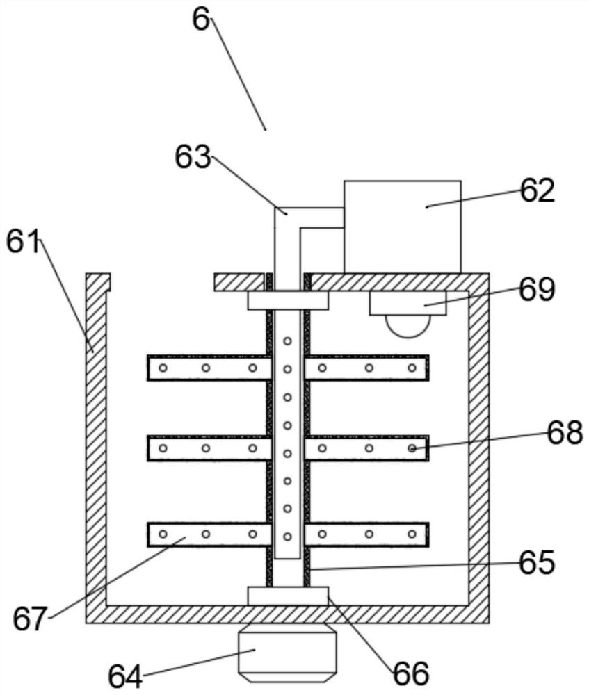
[0026] combine Figure 1-5 , a farm wastewater treatment device, comprising a box body 1, a support block 28 and a base 29, wherein the box body 1 is fixed above the base 29 through the support block 28, a waste water inlet pipe 2 is installed above the box body 1, and the A filter plate 3 is arranged below the wastewater inlet pipe 2, one end of the filter plate 3 is rotatably connected to the vertical plate 4 fixed inside the box body 1, and the other end of the filter plate 3 passes through the L-shaped connector 12 and is fixed in the box body 1 is connected to the spring 11 above the inside, and a fixed rod 13 is fixed on the inner wall on the right side of the box body 1, and a second motor 14 is installed on the fixed rod 13, and a second rotating motor 14 is installed on the output end of the second motor 14. Rod 15, a shifting rod 16 is installed on the second rotating rod 15, a third motor 20 is installed on the vertical plate 4, and a third motor located inside the ...

Embodiment 2

[0038] combine figure 1 and 6 , a farm wastewater treatment device, this embodiment further limits the device on the basis of embodiment 1.

[0039] The detection mechanism 9 includes a detection box 91, a detector 92 and a solenoid valve 93. The detector 92 extends to the inside through the upper part of the detection box 91 and is fixedly connected with the detection box 91. The solenoid valve 93 is respectively installed The solenoid valve 93 is electrically connected to the detector 92 in the fourth pipe and the clean water discharge pipe 10 .

[0040] Specifically, purified water enters the detection mechanism 9 through the second pipeline. When the detector 92 detects that the purified water is qualified, the solenoid valve 93 on the purified water discharge pipe 10 will be opened to discharge the purified water from the inside of the box body 1. If the detector 92 If the 92 detection is unqualified, the electromagnetic valve 93 on the fourth connecting pipe 27 will be...


PUM


Abstract

The invention discloses a farm wastewater treatment device. The device comprises a box body, supporting blocks and a base, wherein the box body is fixed above the base through the supporting blocks; awastewater inlet pipe is mounted above the box body; a filter plate is arranged below the wastewater inlet pipe; one end of the filter plate is rotationally connected with a vertical plate fixed in the box body; the other end of the filter plate penetrates through an L-shaped connecting piece and is connected with a spring fixed at the upper part in the box body; and a fixed rod is fixed to the inner wall of the right side of the box body; a second motor is installed on the fixed rod; a second rotating rod is installed at the output end of the second motor; a shifting rod is installed on thesecond rotating rod; a third motor is installed on the vertical plate; and a third rotating rod located in the extrusion tank is installed at the output end of the third motor. Solid and liquid in thewastewater can be separated out, the solid and the liquid are separately treated, the wastewater treatment efficiency is improved, and the service life of the treatment device is prolonged.

Description

technical field [0001] The invention relates to the technical field of wastewater treatment, in particular to a wastewater treatment device for farms. Background technique [0002] Wastewater treatment is to use physical, chemical and biological methods to treat wastewater, to purify wastewater, so as to achieve wastewater recovery and reuse, and make full use of water resources. [0003] When the farm cleans the breeding house, it will produce a large amount of wastewater, which will directly enter a wastewater reservoir. When the weather is hot, the surrounding area of ​​the wastewater reservoir will emit a disgusting smell, which will affect the surrounding environment of the farm. The existing wastewater treatment device is inconvenient to separate the solids and liquids in the wastewater, which reduces the efficiency of wastewater treatment and reduces the service life of the treatment device. Therefore, a farm wastewater treatment device is needed. Contents of the in...

Claims


Application Information

Patent Timeline
IPC IPC(8): C02F9/08B01D33/03B01D33/64B01D33/80B01F3/04B01F7/18
CPCC02F9/00B01D33/0346B01D33/648B01D33/801C02F1/001C02F1/283C02F1/444C02F1/30C02F7/00C02F2303/04C02F2303/02C02F2103/20B01F23/2331B01F23/23311B01F23/23314B01F23/23761B01F27/11251B01F27/2122B01F27/90B01F2101/305
Inventor 庞俊平
Owner 庞俊平
Learn More