
Recovery method of underground mine goaf remaining studs

A goaf and mine technology, which is applied in the field of mining leftover pillars in goafs of underground mines, can solve the problems of ore dilution, mixing of waste rock, poor operation safety conditions, etc.

Active Publication Date: 2020-10-27
SINOSTEEL MAANSHAN INST OF MINING RES +2
View PDF8 Cites 7 Cited by
  • Summary
  • Abstract
  • Description
  • Claims
  • Application Information

AI Technical Summary

Problems solved by technology

[0007] (1) Only one mining tunnel is arranged for each layer, and the top is the covering layer formed by the collapsed surrounding rock. According to the "ore-drawing ellipsoid theory", when shoveling out the ore, due to the high layering, the When about 1 / 3 to 1 / 2 of the ore is released, waste rocks are mixed in until the released rocks are completely waste rocks, forcing the stop of ore drawing, resulting in permanent loss of ore
[0008] (2) Both sides of the intercolumn are filled with waste rocks. When the ore is shoveled out, the upper part of the ore has not had time to fully release the waste rocks on both sides, and the waste rocks on both sides will start to flow to the mine roadway under the action of its own weight, resulting in serious ore dilution. ;
[0009] (3) Every time shoveling out of the ore is carried out in a single-headed roadway, no penetrating air flow can be formed, the ventilation of the working face is difficult, and the operating safety conditions are poor;
[0010] (4) Each layer uses a fan-shaped medium-deep hole to drop ore and a scraper to remove the ore. It is necessary to move rock drilling and scraper equipment back and forth, and it is necessary to dig a large number of equipment running channels, which greatly increases the amount of accurate cutting work.

Method used


Image

  • Recovery method of underground mine goaf remaining studs
  • Recovery method of underground mine goaf remaining studs
  • Recovery method of underground mine goaf remaining studs

Examples


Embodiment Construction

[0037]In order to describe the present invention better, below in conjunction with accompanying drawing, a kind of mining method of the underground mine goaf leftover column of the present invention will be further described in detail.

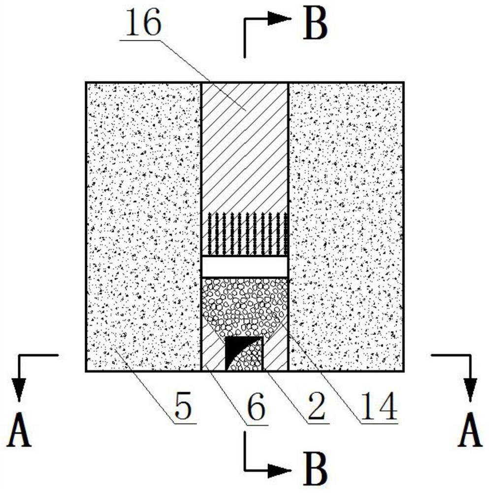
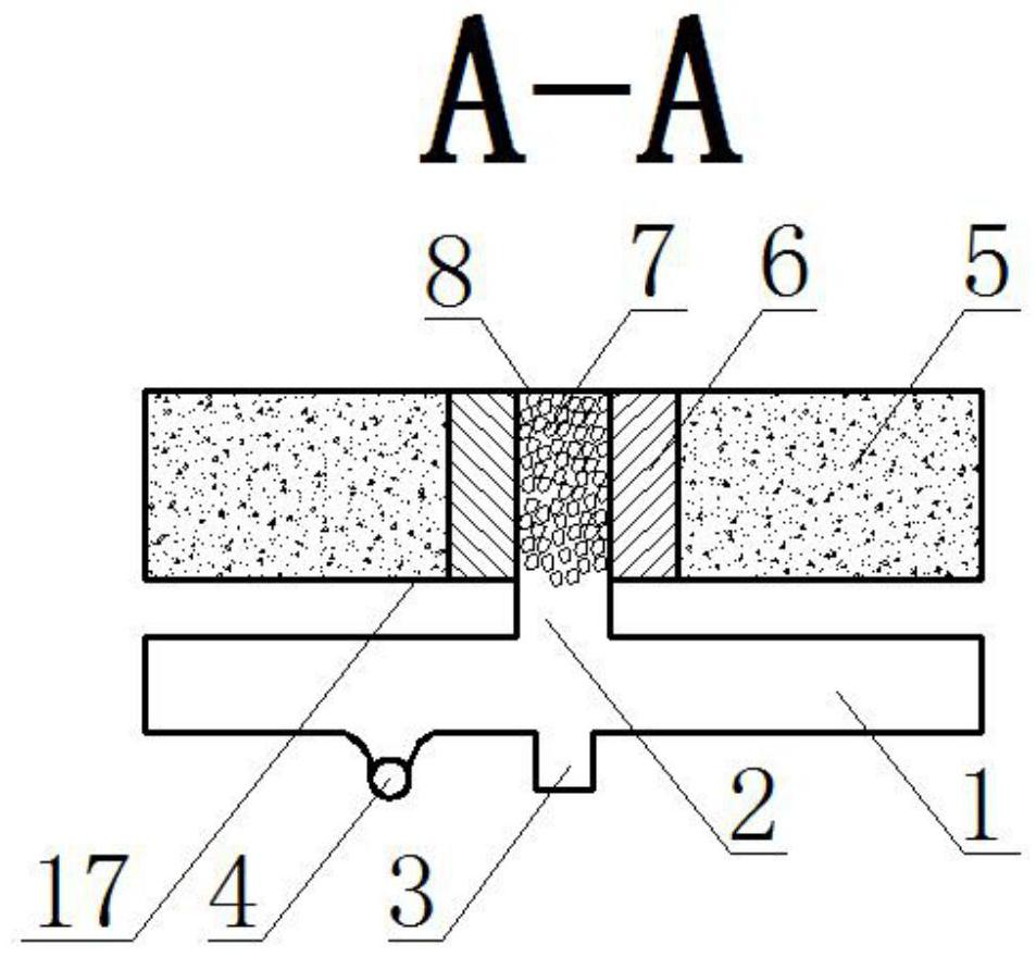
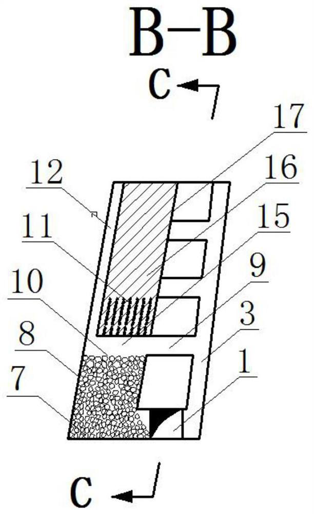
[0038] Depend on figure 1 The front view of the mining method of the left space column in a kind of underground mine mined-out area of ​​the present invention shown and combined figure 2 , image 3 , Figure 4 , Figure 5 , Image 6 It can be seen that the mining method of a kind of underground mine goaf left over pillars in the present invention is provided with pillars 16 in the ore body, and the two sides of pillars 16 are mine houses, and the middle section transportation roadway 1 is provided at the ore body footwall, specifically Implement the following steps:

[0039] 1) When the backing of the mine house is completed and the filling body 5 formed by tailings cemented filling reaches 1.5 MPa, along the direction perpendicular to t...


PUM

PropertyMeasurementUnit
Heightaaaaaaaaaa

Abstract

The invention discloses a recovery method of underground mine goaf remaining studs. The recovery method comprises the following steps that an ore removal roadway is tunneled into a stub (16) on one side of a middle section transportation roadway (1) to reach an ore body hanging wall, and the top of the ore removal roadway is expanded by adopting a fan-shaped medium-length hole to form a horn-mouth-shaped bottom structure; a cutting raise (12) and a pedestrian ventilation raise (3) are arranged in the stud pillar hanging wall ore rock contact face and the footwall surrounding rock respectivelyand communicate with an upper middle section air return roadway, layered connection ways (9) are tunneled in the pedestrian ventilation raise (3) in the vertical direction at intervals of a certain height to reach the stud pillar footwall boundary, the operation links that upward parallel blast holes (11) are drilled layer by layer in circulating mode one by one from bottom to top, charging blasting, forced ventilation and caving ore discharging are conducted till whole interval column is completely mined, then the caved ore (7) is completely discharged through a carry-scraper and fills the goaf, the recovery rate of the stud ore is increased, the ore dilution rate is reduced, and the working environment of a working surface is improved.

Description

technical field [0001] The invention belongs to the technical field of underground mine mining, and in particular relates to a mining method for the left space pillars in goafs of underground mines. Background technique [0002] The mining technical conditions of underground residual ore pillars are extremely complex, which is a major problem in today's mining technology. At present, when many mines recover residual ore resources, they often fail to achieve the expected results due to technical or economic difficulties. [0003] At present, many underground mines at home and abroad use the mining method of empty stop and fill to develop mineral resources. Whether it is the mining method of shallow hole retention and then filling or the method of segmented open stop and fill mining, the ore block is divided into mines and mines. The inter-columns are first returned to the mining room and filled, and then the inter-columns are recovered. This mining method is mainly applicab...

Claims


Application Information

Patent Timeline
IPC IPC(8): E21C41/22E21F15/00E21F1/00F42D3/04
CPCE21C41/22E21F15/00E21F1/006E21F1/00F42D3/04
Inventor 孙国权李宁汪为平肖益盖王雨波李鸿飞刘帅李鹏程
Owner SINOSTEEL MAANSHAN INST OF MINING RES
Learn More