
Structure for independently controlling smoke exhaust of kiln

An independent control and kiln technology, applied in the direction of furnaces, furnace components, exhaust gas devices, etc., can solve problems such as cracking, melting holes, pipes, and valves that are easy to rust

Pending Publication Date: 2020-10-27
DLT TECH CO LTD
View PDF0 Cites 1 Cited by
  • Summary
  • Abstract
  • Description
  • Claims
  • Application Information

AI Technical Summary

Problems solved by technology

[0002] In the existing smoke exhaust method of the kiln, the exhaust gas from the branch pipes above and below the product is generally concentrated to a main pipe on the top of the kiln and then discharged from the exhaust fan. Due to the large interference between the branch pipes during adjustment, the kiln pressure is unstable. The cross-section temperature difference is also large, resulting in product color difference, deformation, cracking, etc.
In addition, the smoke exhaust structure on the upper part of the kiln roof is almost always to open a hole in the kiln roof, and then insert the smoke hood or the top branch pipe into the hole on the kiln roof, because the smoke from the kiln head contains corrosive gases such as sulfur dioxide and dust, Impurities such as steam, and the temperature is high. After a period of use, the pipes and valves are prone to rust and powder collection. When the temperature fluctuates and the alternating hot and cold is large or the adjustment valve vibrates, the rust or sticky matter in the branch pipes will intermittently Falling off to the surface of the product, after high-temperature sintering, defects such as "dirty falling" and "melting holes" will be formed, which will reduce the qualified rate of the product

Method used


Image

  • Structure for independently controlling smoke exhaust of kiln
  • Structure for independently controlling smoke exhaust of kiln
  • Structure for independently controlling smoke exhaust of kiln

Examples


Embodiment Construction

[0021] The concept, specific structure and technical effects of the present invention will be clearly and completely described below with reference to the embodiments and accompanying drawings, so as to fully understand the purpose, characteristics and effects of the present invention. Obviously, the described embodiments are only a part of the embodiments of the present invention, rather than all the embodiments. Based on the embodiments of the present invention, other embodiments obtained by those skilled in the art without creative efforts are all within the scope of The scope of protection of the present invention. In addition, all connection relationships mentioned in the text do not mean that the components are directly connected, but refer to a better connection structure that can be formed by adding or reducing connection accessories according to specific implementation conditions. Various technical features in the present invention can be combined interactively on the...


PUM


Abstract

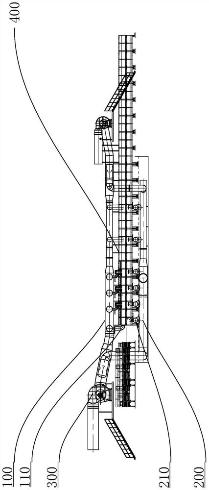
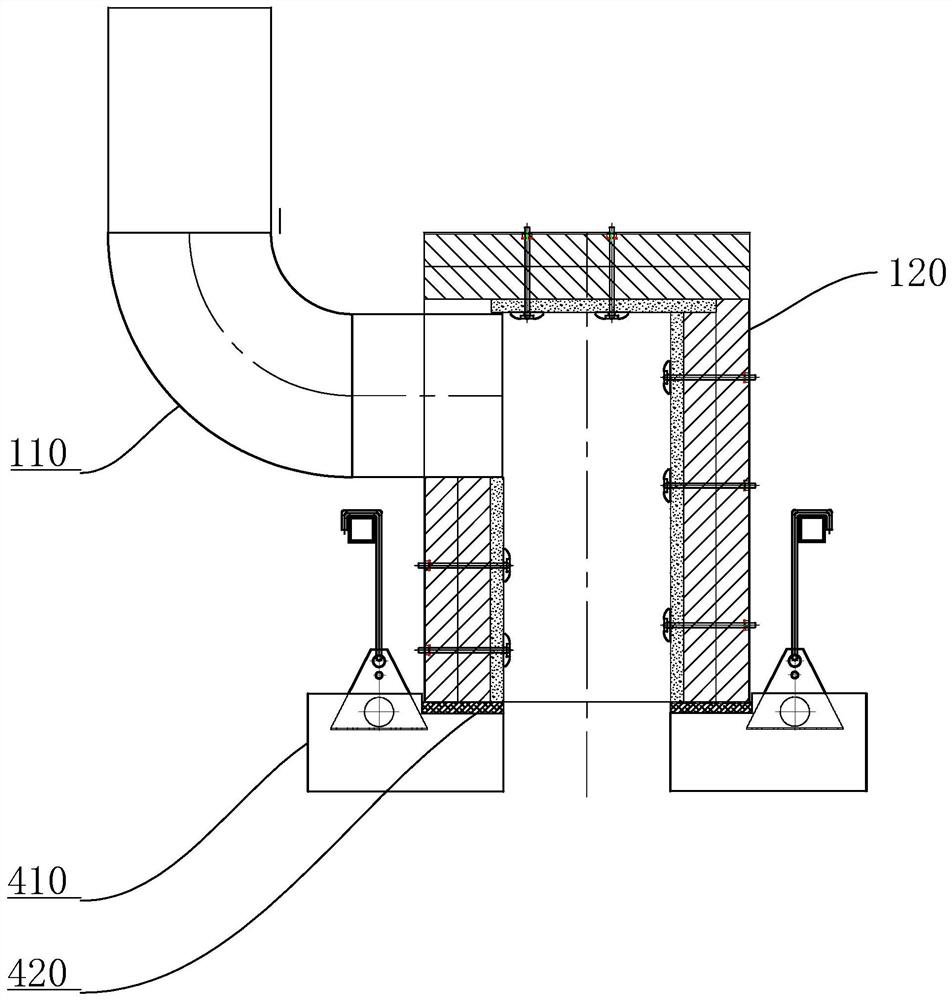
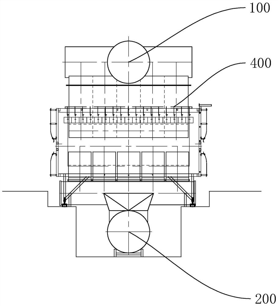
The invention discloses a structure for independently controlling smoke exhaust of a kiln. The structure comprises a kiln body and a smoke exhaust fan, wherein a product upper channel and a product lower channel are formed in the kiln body; an upper smoke exhaust main pipe is arranged at the top of the kiln body; a plurality of upper branch smoke pipes are arranged on the upper smoke exhaust mainpipe; the upper branch smoke pipes communicate with the product upper channel; a lower smoke exhaust main pipe is arranged at the bottom of the kiln body; a plurality of lower branch smoke pipes are arranged on the lower smoke exhaust main pipe; the lower branch smoke pipes communicate with the product lower channel; and the upper smoke exhaust main pipe and the lower smoke exhaust main pipe communicate with the air inlet end of the smoke exhaust fan. According to the structure, the smoke exhaust amount can be increased or decreased according to the temperature conditions of the upper part, the lower part and the section of a product in the kiln body, so that the airflow and the temperature field are changed, the temperature difference problem is solved, and the product defect rate is effectively reduced.

Description

technical field [0001] The invention relates to a kiln, in particular to a structure for independently controlling the smoke exhaust of the kiln. Background technique [0002] In the existing kiln exhaust method, the exhaust gas from the branch pipes above and below the product is generally concentrated to a main pipe at the top of the kiln and then discharged from the exhaust fan. Due to the large interference between the branch pipes during adjustment, the kiln pressure is unstable, and at the same time, the kiln pressure is unstable. The temperature difference of the section is also large, resulting in product color difference, deformation, cracking, etc. In addition, the smoke exhaust structure on the upper part of the kiln roof is almost always opened on the kiln roof, and then the smoke hood or the branch pipe at the top of the kiln is inserted into the hole on the kiln roof. Since the kiln head flue gas contains corrosive gases such as sulfur dioxide and dust, water, ...

Claims


Application Information

Patent Timeline
IPC IPC(8): F27D17/00F23J11/00F23J15/06
CPCF27D17/002F23J11/00F23J15/06
Inventor 程希如陶志坚粱兴强粱伟桦荆海山
Owner DLT TECH CO LTD
Learn More