
High-precision fiber-optic gyro system based on optical fiber temperature measurement and optical fiber loop structure

A fiber optic ring and fiber optic gyroscope technology, applied in thermometers, Sagnac effect gyroscopes, gyroscopes/steering sensing equipment, etc., can solve the problem of affecting the accuracy and full temperature performance of high-precision fiber optic gyroscopes Problems such as real-time performance and accuracy of temperature compensation

Pending Publication Date: 2020-10-27
BEIHANG UNIV
View PDF7 Cites 5 Cited by
  • Summary
  • Abstract
  • Description
  • Claims
  • Application Information

AI Technical Summary

Problems solved by technology

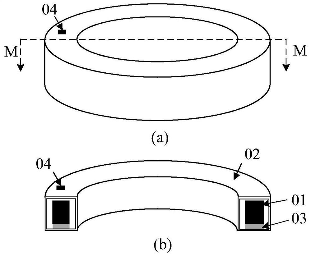
When the ambient temperature changes, the external temperature will first affect the structural part, because only the bonding surface side between the optical fiber ring 01 and the structural part 02 is connected to the structural part 02, and there is a gap between the optical fiber ring 01 and the structural part 02 Adhesive 03, the remaining three sides of the optical fiber ring 01 are not in contact with the structural part 02, the temperature sensor 04 measures the temperature of the structural part 02 in real time, and the ambient temperature is transmitted to the The fiber optic ring 01, so the temperature of the fiber optic ring 01 lags behind that of the structural part 02, which will affect the real-time performance and accuracy of the high-precision fiber optic gyroscope temperature compensation, and ultimately affect the accuracy and full temperature of the high-precision fiber optic gyroscope. performance

Method used


Image

  • High-precision fiber-optic gyro system based on optical fiber temperature measurement and optical fiber loop structure
  • High-precision fiber-optic gyro system based on optical fiber temperature measurement and optical fiber loop structure
  • High-precision fiber-optic gyro system based on optical fiber temperature measurement and optical fiber loop structure

Examples


Embodiment Construction

[0065] The present invention will be further described below in conjunction with the accompanying drawings and examples. It should be understood that the following examples are intended to facilitate the understanding of the present invention, and have no limiting effect on it.

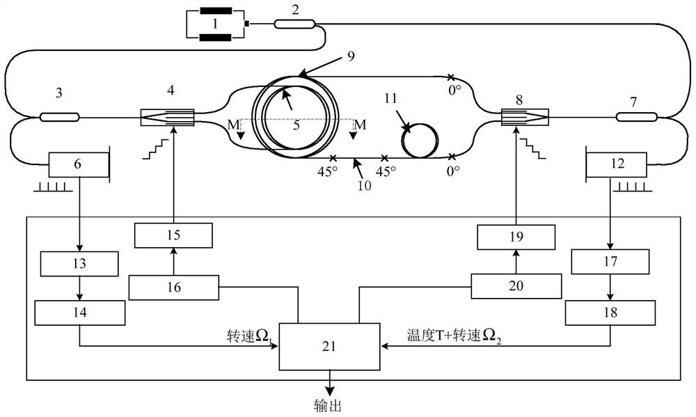
[0066] like figure 2 As shown, the high-precision fiber optic gyro system based on fiber optic temperature measurement provided in this embodiment includes a light source 1, a first coupler 2, a fiber optic gyro, a fiber optic temperature sensor, and a signal processor. The fiber optic gyroscope includes a second coupler 3 , a first Y waveguide 4 , a first fiber optic loop 5 and a first detector 6 , wherein both ends of the first fiber optic loop 5 are welded to the pigtails of the first Y waveguide 4 respectively. The fiber optic temperature sensor includes a third coupler 7, a second Y waveguide 8, a first polarization-maintaining fiber delay loop 9, a polarization-maintaining fiber temperature sen...


PUM


Abstract

The invention relates to the technical field of fiber-optic gyroscopes, in particular to the technical field of high-precision inertial navigation under harsh environmental conditions such as vibration and temperature. The invention discloses a high-precision fiber-optic gyroscope system based on optical fiber temperature measurement, which comprises a fiber-optic gyroscope and a fiber-optic temperature sensor, wherein the fiber-optic gyroscope comprises a first optical fiber loop; and the fiber-optic temperature sensor comprises a second optical fiber loop composed of a first polarization-maintaining optical fiber delay ring, a polarization-maintaining optical fiber temperature sensing head and a second polarization-maintaining optical fiber delay ring, wherein the polarization-maintaining optical fiber temperature sensing head is in close contact with the first optical fiber loop, and the temperature of the optical fiber loop can be accurately measured in real time. According to theinvention, not only the temperature measurement precision is improved, but also the temperature compensation accuracy of the fiber-optic gyroscope is improved, and finally, the precision and the full-temperature performance of the high-precision fiber-optic gyroscope are improved.

Description

technical field [0001] The invention belongs to the technical field of optical fiber gyroscope, and relates to a high-precision optical fiber gyroscope based on optical fiber temperature measurement and an optical fiber ring structure thereof, which can be applied to the technical field of high-precision inertial navigation under severe environmental conditions such as vibration and temperature. Background technique [0002] Fiber optic gyroscope is an angular rate sensor based on the Sagnac effect and optical fiber transmission principle. It has been widely It is used in aviation, aerospace, navigation and weaponry and other fields. [0003] In the structure of the interference fiber optic gyroscope in the prior art, the light wave emitted by the light source is transmitted to the Y waveguide through the coupler, and the Y waveguide divides the input light into two beams of clockwise and counterclockwise transmission after polarizing, and enters the fiber ring connected to ...

Claims


Application Information

Patent Timeline
IPC IPC(8): G01C19/72G01K11/32
CPCG01C19/721G01K11/32Y02A30/00
Inventor 李彦李天琪王鹏跃
Owner BEIHANG UNIV
Learn More