Strength and reliability test device and method for longitudinal roller guide rail mechanism

A technology of roller guide rail and test device, which is applied in the direction of strength characteristics, measuring devices, and the use of stable tension/pressure test material strength, etc., which can solve the problems of bearing pressure, and may also bear tension, proximity, etc.

Active Publication Date: 2020-10-27
中船发动机有限公司
View PDF6 Cites 0 Cited by
  • Summary
  • Abstract
  • Description
  • Claims
  • Application Information

AI Technical Summary

Problems solved by technology

[0004] The inventor found that in order to verify the strength and reliability of the roller guide rail mechanism, its bearing capacity and wear during operation were tested to evaluate the roller guide rail mechanism when it is put into use. Whether the final strength and reliability meet the requirements of use, especially for the longitudinally a

Method used


Image

  • Strength and reliability test device and method for longitudinal roller guide rail mechanism
  • Strength and reliability test device and method for longitudinal roller guide rail mechanism
  • Strength and reliability test device and method for longitudinal roller guide rail mechanism

Examples


Embodiment 1

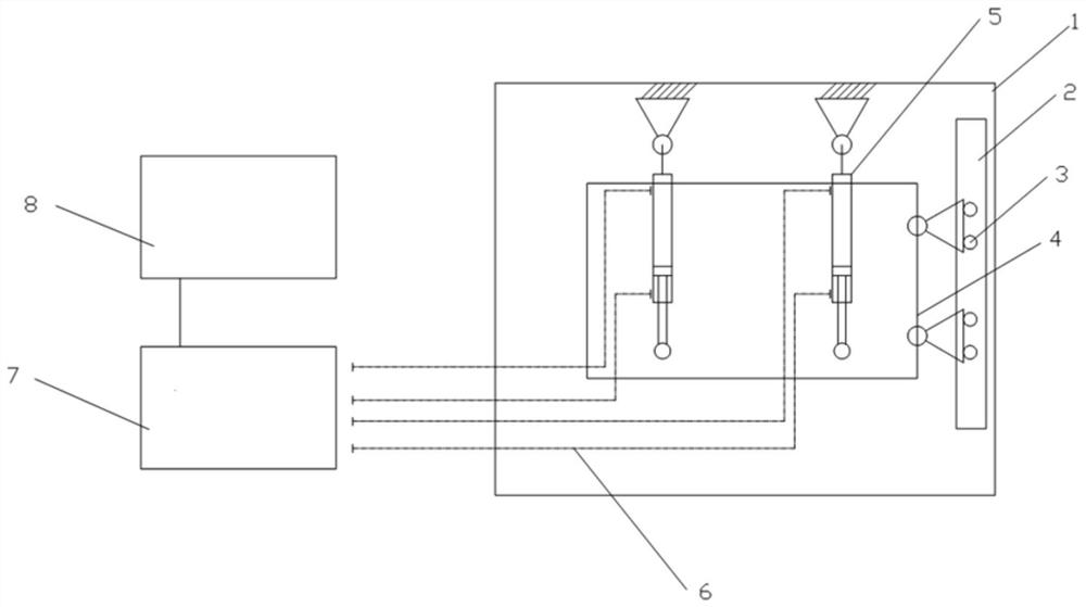
[0029] In a typical embodiment of the present invention, such as figure 1 As shown, this embodiment discloses a strength and reliability test device for a longitudinal roller guide rail mechanism, including a frame 1 fixed on a plane or a workbench and a simulation platform 4 placed inside the frame 1, and the longitudinal guide rail is fixed on the frame 1 , the roller mechanism is fixed on the simulation platform 4, and the roller mechanism and the longitudinal guide rail are slidingly connected to form a roller guide mechanism, so that the simulation platform 4 can move in the vertical direction through the roller guide mechanism.

[0030] More specifically, in this embodiment, the frame 1 is a rectangular parallelepiped frame 1, and the simulation platform 4 moves in the frame 1, so the shape of the simulation platform 4 is limited by the frame 1, and the projection on the plane is also rectangular.

[0031] In this embodiment, what is to be measured is the roller guide ra...

Embodiment 2

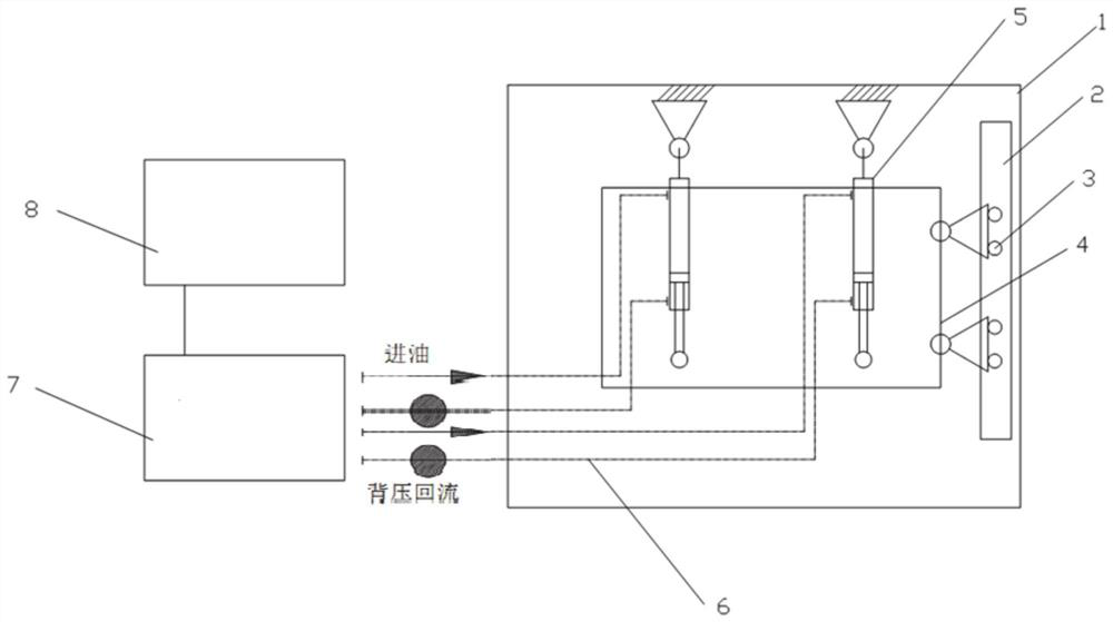
[0049] A strength and reliability test method for a longitudinal roller guide mechanism, using the strength and reliability test device for a longitudinal roller guide mechanism as described in the first aspect, through controlling the expansion and contraction of the hydraulic cylinder 5 multiple times, driving the simulation platform 4 relative to The frame 1 reciprocates to simulate the actual use of the roller guide rail mechanism. The distance sensor used measures the movement height of the simulated platform 4, and the tension and pressure force between the roller and the simulated platform 4 is measured by the pressure sensor.

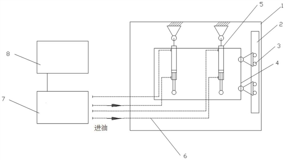
[0050] Wherein, the concrete operating process of hydraulic cylinder 5 is as follows:

[0051] Free Ascent: If figure 2 As shown, the bottom of the two hydraulic cylinders 5 feeds oil, and the top oil returns to open. Under the action of the bottom oil pressure, the simulation platform 4 rises, the head space of the hydraulic cylinders 5 decrea...


PUM


Abstract

The invention discloses a strength and reliability test device and method for a longitudinal roller guide rail mechanism and belongs to the field of physical performance testing. The test device can complete the test of the real stress and operation condition of the roller guide rail mechanism in a laboratory; whether the roller guide rail mechanism meets use requirements is found in advance; serious consequences caused by failure after installation are avoided; the device comprises a frame, a simulation platform and hydraulic cylinders, wherein the simulation platform is connected with the top of the frame through hydraulic cylinders, the hydraulic cylinders can drive the simulation platform to reciprocate in the frame, a roller guide rail mechanism is connected between the frame and thesimulation platform, a distance detector is further arranged between the frame and the simulation platform, a force sensor is arranged between the roller and the simulation platform, and the distancedetector and the force sensor are both connected with a controller.

Description

technical field [0001] The invention belongs to the field of physical performance testing, and in particular relates to a strength and reliability testing device and method for a longitudinal roller guide rail mechanism. Background technique [0002] The statements herein merely provide background information related to the present invention and do not necessarily constitute prior art. [0003] The roller guide mechanism is a common mechanical device, which is widely used in industrial equipment, ships, automobiles, logistics and other fields. For large-scale roller guide rail mechanisms, their load and operating speed are relatively high, so the requirements for their strength and reliability are correspondingly increased. [0004] The inventor found that in order to verify the strength and reliability of the roller guide mechanism, check its bearing capacity and wear during operation to evaluate whether the strength and reliability of the roller guide mechanism after it i...

Claims


Application Information

Patent Timeline
IPC IPC(8): G01N3/10G01N3/36
CPCG01N3/10G01N3/36G01N2203/0003G01N2203/0005G01N2203/0017G01N2203/0019G01N2203/0048G01N2203/0252G01N2203/0641G01N2203/0676G01N2203/0682
Inventor 石冬滨李业鹏刘建飞马钰航
Owner 中船发动机有限公司
Why Eureka
Try Eureka