
IGBT junction temperature estimation system and method based on temperature of emitter power terminal

A power terminal and emitter technology, which is applied in the field of IGBT junction temperature estimation system based on emitter power terminal temperature, can solve the problems of high requirements for measurement circuits and the influence of coupling factors

Pending Publication Date: 2020-10-27
CHAJNA MAJNING DRAJVS EHND AUTOMEHJSHN KO
View PDF9 Cites 4 Cited by
  • Summary
  • Abstract
  • Description
  • Claims
  • Application Information

AI Technical Summary

Problems solved by technology

The heat-sensitive electrical parameter method has the advantages of fast response, high precision, and online measurement, but it has high requirements for the measurement circuit, and there are certain coupling factors, so it needs to be decoupled.

Method used


Image

  • IGBT junction temperature estimation system and method based on temperature of emitter power terminal
  • IGBT junction temperature estimation system and method based on temperature of emitter power terminal
  • IGBT junction temperature estimation system and method based on temperature of emitter power terminal

Examples


Embodiment Construction

[0038] In order to describe the present invention more specifically, the method will be described in detail below in conjunction with the accompanying drawings and specific embodiments.

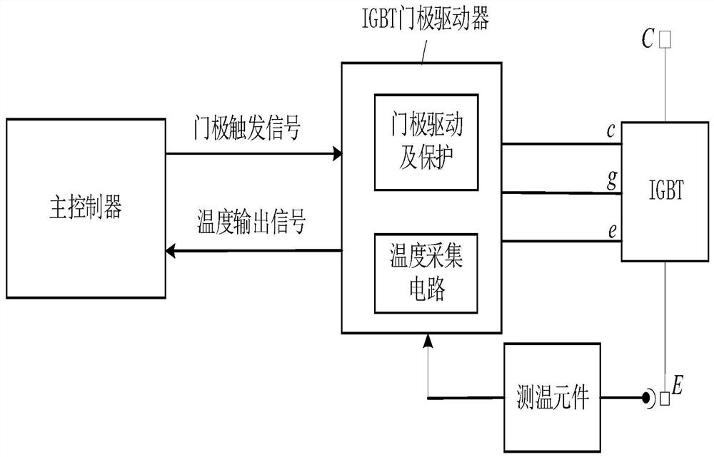
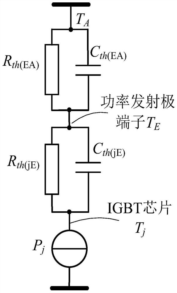
[0039] The present invention proposes a structure diagram of an IGBT junction temperature estimation system based on the temperature of the IGBT emitter power terminal. figure 1 shown. The system mainly includes a temperature measuring element, a temperature acquisition circuit, an IGBT gate driver and a main controller. in,

[0040] The temperature measuring element is used to measure the temperature on the IGBT power emitter terminal;

[0041] IGBT gate drive and protection circuit is used for drive control and protection of power device IGBT;

[0042] The temperature acquisition circuit is arranged on the IGBT gate driver, and is used to acquire the temperature signal on the IGBT power emitter terminal output by the temperature measuring element;

[0043] The main controller is used to s...


PUM


Abstract

The invention provides an IGBT junction temperature estimation system and method based on the temperature of an emitter power terminal. The system comprises a temperature measurement element, a temperature collection circuit, an IGBT gate driver, and a main controller, wherein the temperature measurement element is used for measuring the temperature of an IGBT power emitter terminal, the IGBT gatedriver comprises a gate drive and protection circuit and a temperature acquisition circuit, the gate drive and protection circuit is mainly used for on-off control and short circuit protection of a power device IGBT, the temperature acquisition circuit is used for acquiring a temperature signal, outputted by the temperature measurement element, on the IGBT power emitter terminal, and the main controller is used for sending a gate trigger signal to the IGBT gate driver, receiving a temperature signal on the IGBT power emitter terminal transmitted by the IGBT gate driver, and estimating the IGBT junction temperature according to the temperature signal on the IGBT power emitter terminal. According to the system, the over-temperature protection of the IGBT is realized, and IGBT temperature estimation is realized on the controller side.

Description

technical field [0001] The invention relates to the technical field of power electronics, in particular to a system and method for estimating the junction temperature of an IGBT based on the temperature of an emitter power terminal. Background technique [0002] With the development of the power electronics technology industry, the insulated gate bipolar transistor (IGBT), as the core semiconductor device for energy conversion and transmission, has become more and more widely used. When the power converter system is running, the temperature of the chip will rise due to the switching loss and conduction loss of the IGBT, which will cause the internal materials of the IGBT to suffer thermal stress, accelerate the aging degree and failure rate of the device, and cause the converter to fail. Therefore, the estimation of junction temperature of IGBT is of great significance to its reliability, health status and service life evaluation. [0003] The existing IGBT module internal ...

Claims


Application Information

Patent Timeline
IPC IPC(8): G01R31/26H02H7/20
CPCG01R31/2619H02H7/205
Inventor 谭国俊张经伟耿程飞封安波
Owner CHAJNA MAJNING DRAJVS EHND AUTOMEHJSHN KO
Learn More