
Multi-rotor unmanned aerial vehicle motor inclination angle and installation tolerance constraint determination method

A multi-rotor unmanned, method-determined technology, applied in the direction of non-electric variable control, instrument, attitude control, etc., can solve the problems of insignificant quality improvement, loss of motor tension, and influence on pitch and roll channel attitude control, etc.

Inactive Publication Date: 2020-10-27
TOPXGUN NAN JING ROBOTICS CO LTD
View PDF0 Cites 0 Cited by
  • Summary
  • Abstract
  • Description
  • Claims
  • Application Information

AI Technical Summary

Problems solved by technology

If the inclination angle of the motor is too small, the quality improvement will not be obvious; if the inclination angle of the motor is too large, it will cause loss of motor tension, and even affect the pitch and roll channel attitude control
[0003] In the existing technology, technicians usually adjust the inclination angle of the motor on the UAV based on work experience, but different UAVs have different constraints and parameters, and it is undoubtedly very different to adjust the inclination angle of the motor only through experience. Deterministic; therefore, accurate motor mounting inclination and tolerance constraints are important

Method used


Image

  • Multi-rotor unmanned aerial vehicle motor inclination angle and installation tolerance constraint determination method
  • Multi-rotor unmanned aerial vehicle motor inclination angle and installation tolerance constraint determination method
  • Multi-rotor unmanned aerial vehicle motor inclination angle and installation tolerance constraint determination method

Examples


Embodiment 1

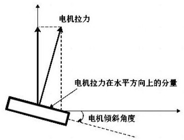
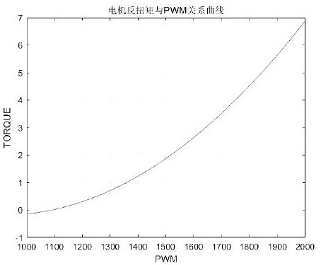
[0069] Such as figure 1 As shown, the yaw control principle of the multi-rotor is to use the reaction torque (reverse torque) of the motor to generate the yaw moment, and then form the yaw motion. When the motor is installed horizontally, the yaw torque is small and the yaw response is slow. Therefore, the strategy of motor tilt is adopted to generate yaw torque by using the component of the motor pulling force in the horizontal direction, and superimposed with the counter torque of the motor to produce the final Yaw moment to speed up yaw response.

[0070] It should be noted that before determining the inclination angle of the motor and the installation tolerance range of the inclination angle, carry out horizontal calibration and magnetic compass calibration, and keep the drone in a full-load hovering state to ensure that the environment is windless and magnetically disturbed, and the consistency of the propellers passes.

[0071] Based on the model parameters of a plant p...

Embodiment 2

[0099] On the basis of the first embodiment above, the steps of obtaining the motor installation tolerance in this embodiment are as follows:

[0100] Constraints: In the hovering state, the maximum speed difference between positive and negative propellers caused by compensating for motor installation tolerances is ±2.5%, and the motor tilt angle is 5.5°.

[0101] The tension required for a single axis hovering with full load is

[0102]

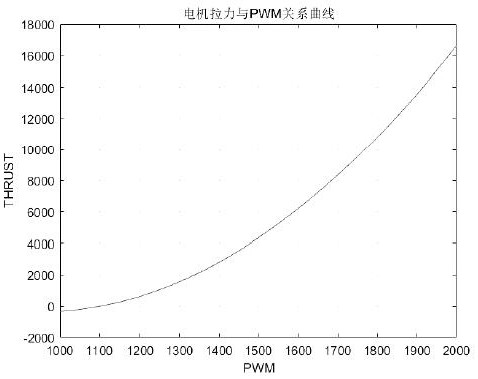
[0103] According to the throttle pull curve, the standard throttle pwm is 1741 at this time.

[0104] Assuming that the consistency of the positive and negative propellers is good, ignoring the influence caused by the unbalanced tension and torque, when the flight control output speed difference is ±2.5% as the inspection standard, it can be seen that the positive and negative propellers deviate from each other by 2.5% to both sides of the reference throttle pwm, that is, 25us The pwm value, the pwm changes as follows:

[0105]

[01...

Embodiment 3

[0124] This embodiment provides the comparison test when the motor is horizontal and when the motor is inclined at 5.5 degrees. Figure 7 It shows that the yaw angular acceleration reaches the maximum constraint condition when the inclination angle of the motor is not added At this time, the pwm values ​​of the four motors, among which the difference between No. 1 and No. 3 motors and No. 3 and No. 4 motors is 400us, that is, the deviation reaches ± 20%, which does not meet the design requirements.

[0125] Figure 8When adding a 5.5° motor tilt angle, the yaw angular acceleration reaches the maximum constraint condition When the pwm value of the four motors, the difference between No. 1 and No. 3 motors and No. 3 and No. 4 motors is 220us, that is, the deviation reaches ±11%, which meets the design requirements.


PUM


Abstract

The invention discloses a multi-rotor unmanned aerial vehicle motor inclination angle and installation tolerance constraint determination method. The method specifically comprises the following steps:step 1, formulating flight control design indexes according to controllability requirements of attitude channel control distribution and performance requirements of yaw response; step 2, establishinga yaw channel kinetic model with a motor inclination angle according to a motor tension curve and a torque curve of the whole machine and a part of machine type parameters; 3, determining a motor inclination angle according to the yaw channel dynamic model and the flight control design indexes; and step 4, determining an inclination angle installation tolerance range according to the motor inclination angle and a hovering state maximum motor rotating speed difference design index. By quantitatively determining the installation inclination angle of the motor, the yaw response is accelerated, the yaw anti-interference capability is enhanced, and the control quality is improved; the rotating speed difference required by yawing is reduced, and the control allowance of pitching and rolling channels is increased; and by determining tolerance constraints during inclination angle installation of the motor, the risk of unbalance of the rotating speed of the motor is reduced, and the flight control quality is improved.

Description

technical field [0001] The invention relates to the field of unmanned aerial vehicles, in particular to a method for determining the inclination angle of a motor of a multi-rotor unmanned aerial vehicle and an installation tolerance constraint. Background technique [0002] In the design of the whole machine, the method of increasing the inclination angle of the motor installation is usually used to speed up the response of the yaw channel, reduce the proportion of the yaw channel in the control distribution, increase the control margin of the pitch and roll channels, and improve the quality of attitude control. If the inclination angle of the motor is too small, the quality improvement will not be obvious; if the inclination angle of the motor is too large, it will cause loss of motor tension, and even affect the pitch and roll channel attitude control. [0003] In the existing technology, technicians usually adjust the inclination angle of the motor on the UAV based on wor...

Claims


Application Information

Patent Timeline
Patent Type & Authority Applications(China)
IPC IPC(8): G05D1/08G05D1/10B64D27/40
CPCG05D1/0825G05D1/101
Inventor 孟晨蒋元庆
Owner TOPXGUN NAN JING ROBOTICS CO LTD
Learn More