
Dynamic progressive failure analysis method for composite material multi-scale model

A composite material, failure analysis technology, applied in CAD numerical modeling, constraint-based CAD, special data processing applications, etc., can solve problems such as observation and understanding of mechanical, machining deformation, material failure, etc.

Pending Publication Date: 2020-10-27
NANJING UNIV OF AERONAUTICS & ASTRONAUTICS
View PDF0 Cites 6 Cited by
  • Summary
  • Abstract
  • Description
  • Claims
  • Application Information

AI Technical Summary

Problems solved by technology

[0002] In order to reduce the damage to the composite material structure under dynamic load conditions, the traditional and simple and direct research method relies on experimental analysis, but the traditional method still has a lot of shortcomings, such as long preparation time, large material consumption, The cost is high, and more importantly, it is impossible to observe and understand the mechanisms of mechanical deformation and material failure from a microscopic perspective

Method used


Image

  • Dynamic progressive failure analysis method for composite material multi-scale model
  • Dynamic progressive failure analysis method for composite material multi-scale model
  • Dynamic progressive failure analysis method for composite material multi-scale model

Examples


Embodiment Construction

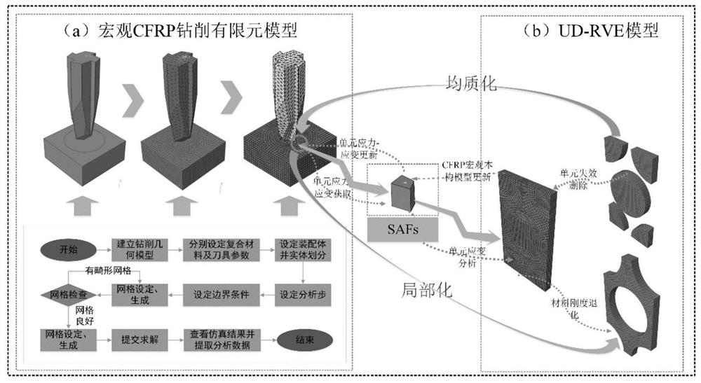
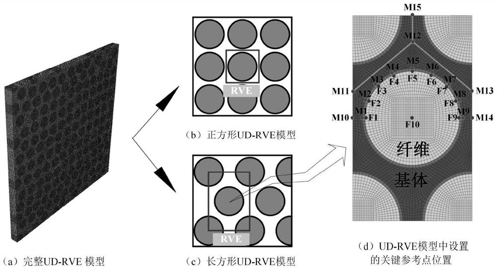
[0026] The macroscopic stress of the composite laminate structure and the microscopic stress of each component structure are bridged by the stress amplification factor, and the stress amplification factor can be obtained by the finite element analysis result of the representative volume element containing the fiber and the matrix. After the stress amplification factor is obtained, the macro-micro conversion equation is used to realize the conversion of macro-stress to micro-stress. The expression of the macro-micro conversion equation is shown in equations (1), (2), (3):

[0027]

[0028]

[0029]

[0030] In formulas (1)~(3): σ i Indicates the stress at n points of the fiber or matrix, where n is the stress analysis point, i=1~6; Represents the macroscopic stress component of the composite laminate, j = 1~6; It is expressed as the stress amplification factor under the action of the mechanical load at n points, p=1-6, k=1-6.

[0031] Based on the failure theory of micromechanics, ...


PUM


Abstract

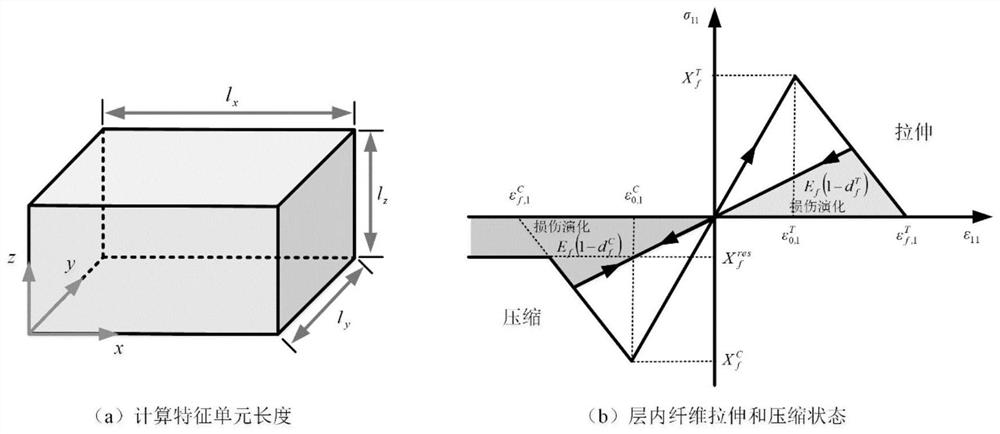
The mechanical response and progressive damage behaviors of the composite material laminated plate structure generated under the dynamic working condition are studied. Firstly, different mechanical behaviors of fibers and a matrix in a microscopic state are considered, and a three-dimensional multi-scale dynamic progressive damage evolution law model based on a microscopic failure theory is provided. Based on micro-component degradation elastic parameters in a typical representative volume unit model, a novel fiber and resin matrix damage evolution rule model and a failure unit auxiliary deletion criterion are provided; and secondly, a relationship model of macroscopic stress and representative volume unit microcosmic stress in the composite material model is built by adopting a stress amplification coefficient, and thus simulating in-layer and interlayer damage behaviors of the composite material under the cutting action of the dagger drill in combination with a bilinear cohesive force unit model.

Description

Technical field [0001] The invention relates to the field of mechanical response and progressive damage generated under dynamic load conditions of a composite material laminated plate structure. Background technique [0002] In order to reduce damage to composite structures under dynamic loading conditions, traditional and simple and direct research methods rely on experimental analysis, but traditional methods still have a lot of shortcomings, such as long preparation time, large material consumption, The cost is higher, and more importantly, it is impossible to observe and understand the mechanism of mechanical processing deformation and material failure from the microscopic view. Summary of the invention [0003] The present invention provides a three-dimensional multi-scale dynamic progressive damage evolution model based on micro-failure criteria. The relationship between macro-stress and micro-stress is established by using the stress amplification factor, and the structural...

Claims


Application Information

Patent Timeline
IPC IPC(8): G06F30/23G06F111/04G06F111/10G06F113/26G06F119/14G06F119/02
CPCG06F30/23G06F2111/04G06F2111/10G06F2113/26G06F2119/14G06F2119/02
Inventor 齐振超刘勇王星星陈文亮肖叶鑫姚晨熙李丰辰张子亲
Owner NANJING UNIV OF AERONAUTICS & ASTRONAUTICS
Learn More