Display screen structure

A technology of display screen and transparent display screen, which is applied in optics, instruments, nonlinear optics, etc., and can solve the problems of reduced display effect

Pending Publication Date: 2020-10-27
SHENZHEN KNQ SCI & TECH CO LTD
View PDF0 Cites 0 Cited by
  • Summary
  • Abstract
  • Description
  • Claims
  • Application Information

AI Technical Summary

Problems solved by technology

[0004] The purpose of the present invention is to provide a display screen structure, which aims to solve the problem in the prior art that the

Method used


Image

  • Display screen structure
  • Display screen structure
  • Display screen structure

Examples


Embodiment 1

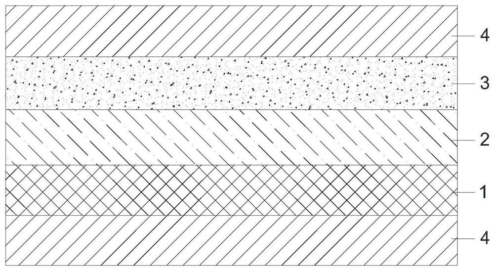
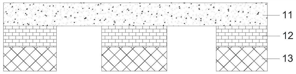
[0028] like figure 1 and image 3 As shown, the above-mentioned transparent display screen 1 may include a transparent base layer 11, a circuit layer 12 and an LED lamp group 13, wherein the circuit layer 12 is arranged on the front side of the transparent base layer 11, and the LED lamp group 13 is arranged on the front side of the circuit layer 12 side, and the LED lamp group 13 is electrically connected to the circuit layer 12 . In addition, the above-mentioned polymer dispersed liquid crystal display layer 2 is disposed on the reverse side of the transparent base layer 11 , and at the same time, the front side of the LED lamp group 13 is covered with the first protective layer 4 . In this embodiment, the circuit layer 12 can be a metal grid circuit layer, a nano-silver wire circuit layer, an indium tin oxide (Indium tin oxide, ITO) circuit layer, or a flexible copper clad laminate (Flexible Copper Clad Laminate, FCCL) circuit layer. of any kind. For example, the transpa...

Embodiment 2

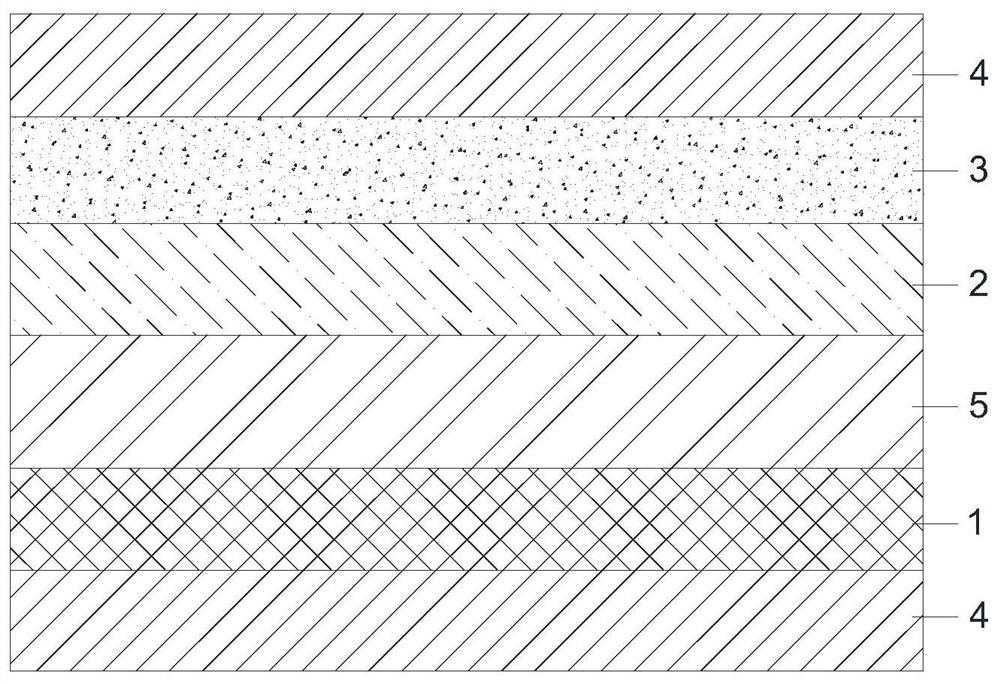
[0030] like figure 2 As shown, a layer of first protective layer 4 is provided on the reverse side of the above-mentioned transparent explosion-proof layer 3, and a layer of first protective layer 4 is also provided on the front side of the transparent display screen 1. At the same time, the above-mentioned transparent display screen 1 and the above-mentioned polymer A second protective layer 5 is arranged between the dispersed liquid crystal display layers 2 . In this embodiment, the first protective layer 4 and the second protective layer 5 are the same, and both may be any one of a transparent glass layer, a transparent adhesive layer, a transparent ink layer, and a transparent film layer. In this embodiment, the purpose of setting the first protective layer 4 on the opposite side of the transparent explosion-proof layer 3 is mainly to increase the flexibility and hardness of the product and protect the product from damage. In application scenarios requiring high flexibil...


PUM


Abstract

The invention relates to the field of transparent display screens, and provides a display screen structure. The display screen structure comprises a transparent display screen, a polymer dispersed liquid crystal display layer arranged on the reverse side of the transparent display screen, a transparent explosion-proof layer arranged on the reverse side of the polymer dispersed liquid crystal display layer, and first protective layers arranged on the reverse side of the transparent explosion-proof layer and the front side of the transparent display screen respectively. The invention provides the display screen structure, a polymer dispersed liquid crystal display layer is arranged on the reverse side of the transparent display screen; the polymer dispersed liquid crystal display layer can generate an atomization effect when being electrified; the transparent effect is shown when the power is not on; thus, the display screen structure is irradiated by high light; in an environment wherehigh light illuminates the display screen structure the polymer dispersed liquid crystal display layer is powered on to form the atomization surface, so that high light cannot penetrate through the display screen structure, the display effect is improved, in addition, the transparent effect is achieved when the polymer dispersed liquid crystal display layer is not powered on, the overall transparent effect of the display screen structure is achieved, and the display function of the display screen structure is enriched.

Description

technical field [0001] The present invention relates to the technical field of transparent display screens, and more specifically relates to a display screen structure. Background technique [0002] LED transparent screen is one of the LED display screens, and its light source is LED lamp beads. Compared with the traditional LED screen field, the main characteristics of LED transparent screen are high transmittance, light weight of the screen body, and seamless splicing of the screen body. , The size can be expanded infinitely in principle, the installation is mainly attached to the back of the glass curtain wall or the glass window, indoor installation, outdoor viewing, and the structure is simple, the visible light transmittance is more than 85%. [0003] With the rise of the definition of "new retail" in China, the digital signage industry symbolized by retail is expanding rapidly. LED transparent screens play a major role in commercial retail window, interior decoration ...

Claims


Application Information

Patent Timeline
IPC IPC(8): G09F9/33G02F1/1334
CPCG02F1/1334G09F9/33
Inventor 由龙张林杰赵伟业
Owner SHENZHEN KNQ SCI & TECH CO LTD
Why Eureka
Try Eureka