
Visible light communication system and sending end, receiving end and method thereof

A visible light communication and sending end technology, applied in the field of optical communication, can solve the problems of complex technology and high cost, and achieve the effect of simple technology, low cost and improved scalability

Pending Publication Date: 2020-10-27
OPPLE LIGHTING +1
View PDF0 Cites 0 Cited by
  • Summary
  • Abstract
  • Description
  • Claims
  • Application Information

AI Technical Summary

Problems solved by technology

[0003] In some visible light communication technologies in the prior art, in order to superimpose the light wave emitted by the lighting device in the visible light communication system with the communication signal wave, it is necessary to carry out coding transformation on the driving of the lighting device, which is complicated and costly.

Method used


Image

  • Visible light communication system and sending end, receiving end and method thereof
  • Visible light communication system and sending end, receiving end and method thereof
  • Visible light communication system and sending end, receiving end and method thereof

Examples


Embodiment Construction

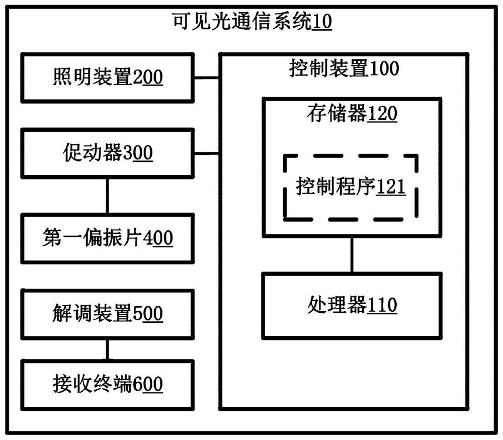
[0036] figure 1 is a schematic diagram of a visible light communication system 10 according to an embodiment of the present invention.

[0037] The visible light communication system 10 of this embodiment can be applied to working environments with large-scale lighting equipment such as libraries, laboratories, gymnasiums, and museums, and is used to support the interconnection and intercommunication between various devices in the working environment, for example, to control each device or positioning etc.

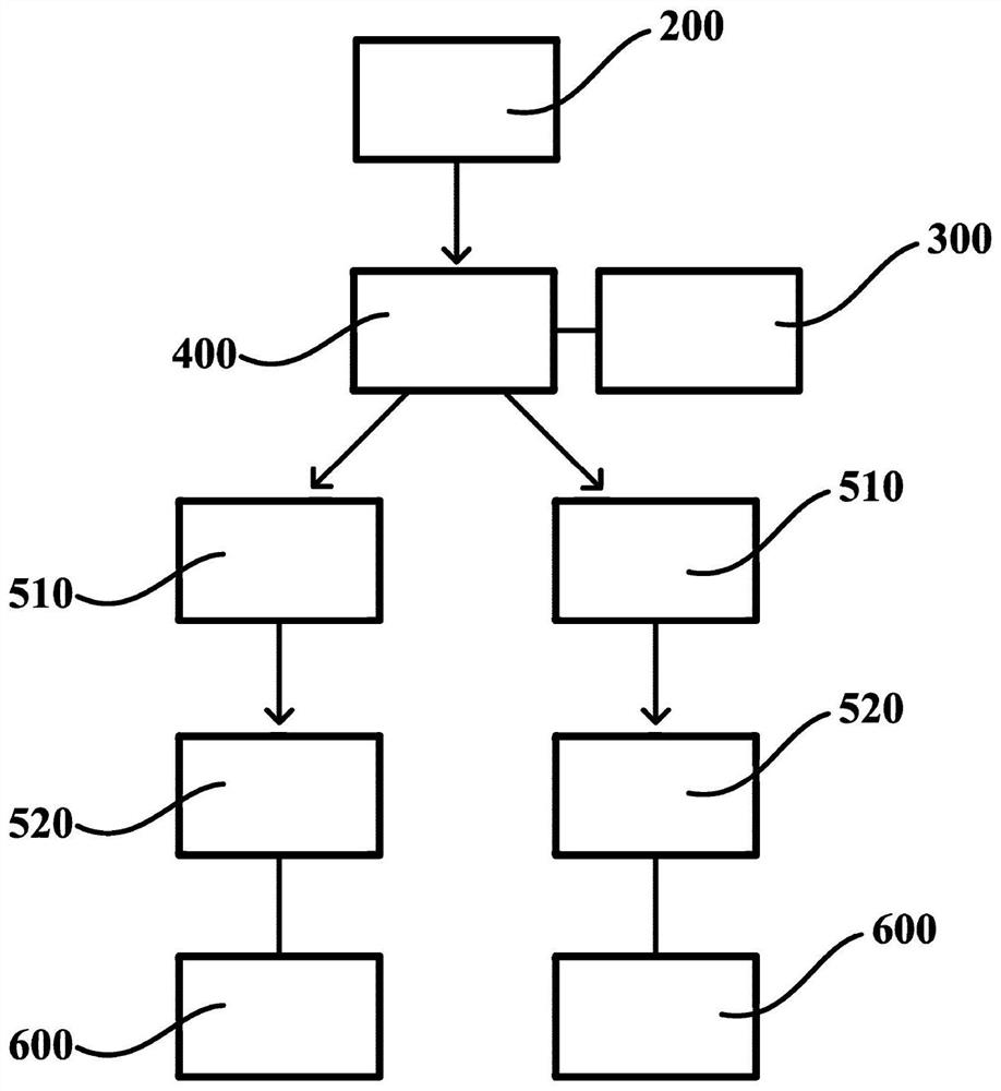
[0038] The visible light communication system 10 may generally include a sending end and a receiving end. Wherein, the sending end may include the lighting device 200 , the first polarizer 400 , the actuator 300 , and may further include the control device 100 . The receiving end may include a demodulation device 500 and a receiving terminal 600 . Wherein, the sending end forms a signal sending end of the visible light communication system 10 for generating communicatio...


PUM


Abstract

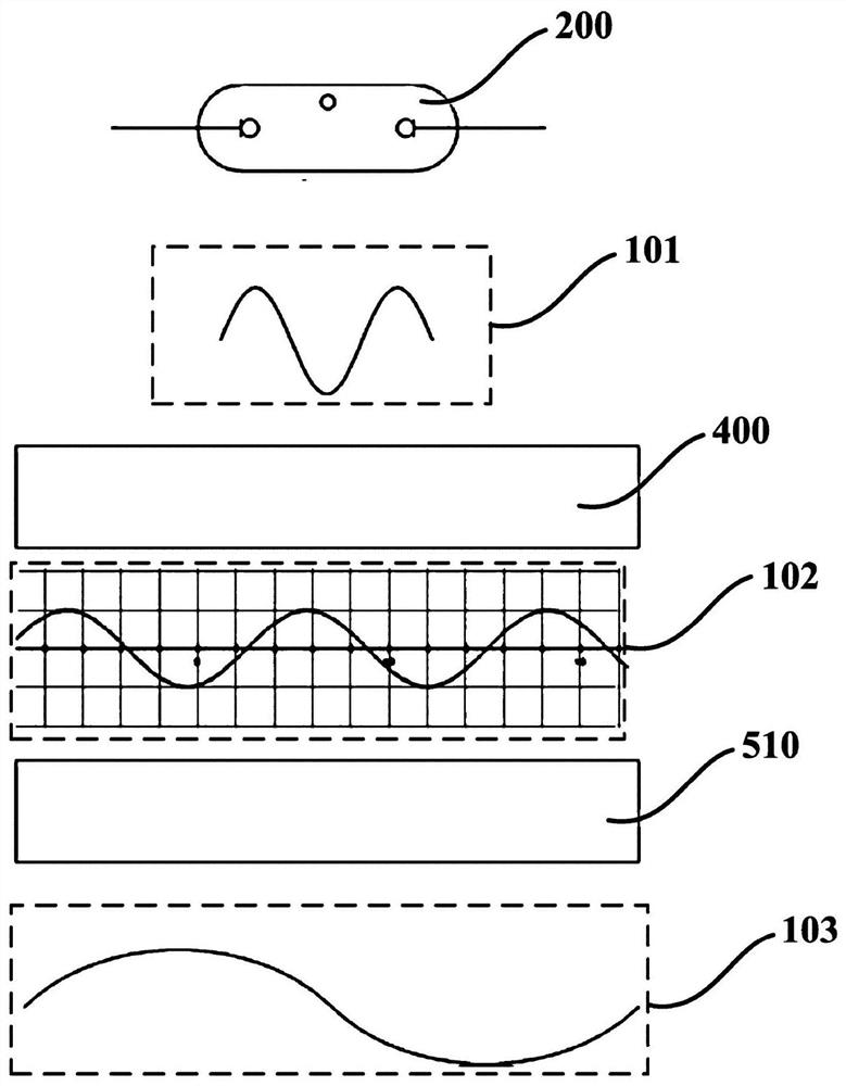
The invention provides a visible light communication system and a sending end, a receiving end and a method thereof, and the sending end of the visible light communication system comprises an illumination device used for providing illumination light; a first polaroid which is arranged on the propagation path of the illumination light in a variable-frequency rotating manner and is used for carryingout frequency modulation on the passing illumination light, so that the illumination light carries a communication signal; and an actuator which is in transmission connection with the first polaroidso as to drive the first polaroid to rotate. According to the visible light communication system and the sending end, the receiving end and the method thereof, the illumination light emitted by the illumination device can carry the communication signal under the condition that the drive of the illumination device does not need to be coded and transformed, the technology is simple, and the cost islow.

Description

technical field [0001] The present invention relates to optical communication technology, in particular to a visible light communication system, a sending end, a receiving end and a method thereof. Background technique [0002] Optical communication is a communication method with light waves as the carrier, and visible light communication (Visible Light Communication, VLC) refers to a communication method that uses high-speed bright and dark flickering signals that are invisible to the naked eye emitted by fluorescent lamps and other lighting devices as communication signals to transmit information. [0003] In some visible light communication technologies in the prior art, in order to superimpose the light wave emitted by the lighting device in the visible light communication system with the communication signal wave, it is necessary to modify the coding of the driving of the lighting device, which is complicated and costly. [0004] Therefore, how to provide a visible ligh...

Claims


Application Information

Patent Timeline
Patent Type & Authority Applications(China)
IPC IPC(8): H04B10/116H04B10/50H04B10/60
CPCH04B10/116H04B10/50H04B10/60
Inventor 江磊罗顺
Owner OPPLE LIGHTING
Learn More