Quantum secret sharing method and system based on differential phase shift

A quantum secret and differential phase shift technology, which is applied in transmission systems, digital transmission systems, and key distribution, can solve problems such as short transmission distance, poor security, and low coding rate, and achieve improved key coding rate and transmission distance , resist independent attacks, and highly operable

Active Publication Date: 2020-10-27
NANJING UNIV
View PDF5 Cites 5 Cited by
  • Summary
  • Abstract
  • Description
  • Claims
  • Application Information

AI Technical Summary

Problems solved by technology

However, this solution still has the problems of poor security, low coding rate, short transmission distance and difficulty in practical application.
Despite more than 20 years of effort, there are still fundamental constraints to the practical application of quantum secret sharing

Method used


Image

  • Quantum secret sharing method and system based on differential phase shift
  • Quantum secret sharing method and system based on differential phase shift
  • Quantum secret sharing method and system based on differential phase shift

Examples


Embodiment 1

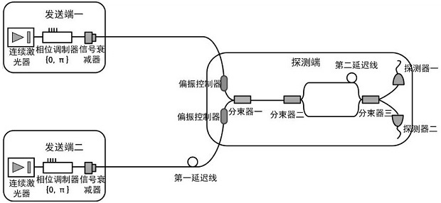
[0057] The three parties are Alice, Bob and Charlie. Wherein Alice and Bob have the same equipment, but the optical fiber distance from Alice to the beam splitter 1 used for beam combining is longer, so as to delay time. Both of them use CW lasers to generate phase-stabilized time-continuous pulsed optical signals. Phase encoding is performed by a phase modulator, phase modulation 0 corresponds to logic bit 0, and phase modulation Corresponds to logic bit 1. Both of them send quantum states with a period of 2 nanoseconds (ns). The moment when Alice arrives at beam splitter 1 is longer than the relaxation time of Bob’s signal T. They are respectively adjusted to two beams with the same polarization direction by polarization controller 1 and polarization controller 2. After the light pulses are combined by a beam splitter, the beams are sent to the detection end Charlie.

[0058] Charlie's beam splitter 2 and beam splitter 3 constitute an unbalanced Mach-Zehnder interferomet...

Embodiment 2

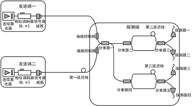
[0066] In Embodiment 1, beam splitter 1 is used to combine beams, and only pulses from one port are used, which wastes half of the photons that can be used for coding.

[0067] combine figure 2 , compared with Embodiment 1, this embodiment also adds a set of detection units that are the same as the detection end in Embodiment 1 at the other port of beam splitter 1. The probability of two sets of detection units responding at the same time is very small and can be ignored. The specific operation is the same as that in Embodiment 1. In this way, the number of photons is effectively utilized, and the efficiency is nearly doubled compared with the first embodiment.

Embodiment 3

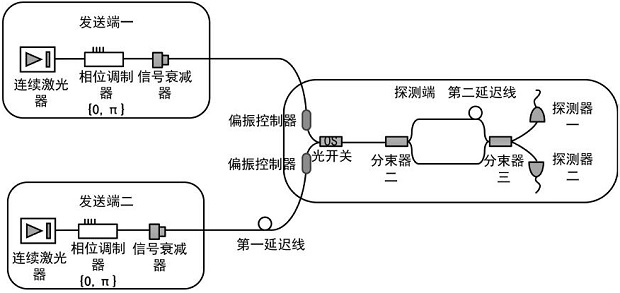
[0069] In the second embodiment, too many devices are used and the operation is relatively complicated. In this embodiment, the beam splitter 1 used for beam combining is replaced with an optical switch. An optical switch combines two optical pulses into a single-mode fiber.

[0070] combine image 3 , Alice and Bob send weakly coherent states with the same polarization direction. Since the pulses sent by Alice and Bob are one after the other in one cycle, when an optical pulse reaches the optical switch, the optical switch will let it pass, so that the two A beam of light pulses is combined into a single-mode fiber. The rest of the operations are the same as in the first embodiment, and the coding rate in the third embodiment is the highest compared with the first and second embodiments.

[0071] To sum up, quantum secret sharing is performed according to the image in Embodiment 3, and the final coding rate is calculated according to the following formula:

[0072]

[0...


PUM


Abstract

The invention discloses a quantum secret sharing method and system based on differential phase shift, the system comprises a sending end, a detection end and the like, the detection end comprises a receiving unit and a detection unit, the receiving unit comprises a polarization controller and a beam splitter used for beam combination, and the detection unit comprises an unbalanced interferometer and a pair of detectors. The detection end performs detection response according to the interference result and only publishes the response time of each detector, and calculates the gain for coding according to the transmitted data volume and the detection count; the sending ends respectively form original secret keys which are not subjected to post-processing according to the response moments; andthen the detection end randomly selects a plurality of response moments, calculates a system error rate according to a preset rule, and finally performs post-processing on the original key, so that the sending end I and the sending end II share the key of the detection end. Quantum secret sharing between the two sending ends and the detection end can be achieved, the secret key safety is high, and meanwhile the secret key code forming rate and the transmission distance are further increased.

Description

technical field [0001] The invention relates to the technical field of quantum communication, in particular to a quantum secret sharing method and system based on differential phase shift. Background technique [0002] The earliest quantum secret sharing protocol is the HBB protocol based on GHZ state distribution proposed by Hillery M et al. in 1999. (Physical Review A 59(3): 1829.) However, because the GHZ state itself is difficult to prepare, the HBB protocol has always had problems such as low coding rate, complicated experimental equipment, and difficult experimental implementation, so it cannot be put into practical use. Later, in order to solve this problem to a certain extent, the first measurement device-independent quantum secret sharing scheme (MDI-QSS) using post-selected GHZ states was proposed by the inventor team (Physical review letters 114(9): 090501. ). However, this scheme still has the problems of complex experimental equipment, cumbersome experimental ...

Claims


Application Information

Patent Timeline
Patent Type & Authority Applications(China)
IPC IPC(8): H04L9/08
CPCH04L9/0852H04L9/0858
Inventor 尹华磊顾杰陈增兵
Owner NANJING UNIV
Why Eureka
Try Eureka