
Fryer

A fryer and pot body technology, applied in the field of fryer, can solve the problems of unstable edible oil quality, low heating efficiency, short service life, etc.

Pending Publication Date: 2020-10-30
浙江超太环保设备有限公司
View PDF0 Cites 0 Cited by
  • Summary
  • Abstract
  • Description
  • Claims
  • Application Information

AI Technical Summary

Problems solved by technology

[0006] In order to solve the technical problems of low heating efficiency, discontinuous frying process, unstable edible oil quality and short service life caused by frying carbonization in the prior art, the present invention provides a fryer, which includes a fryer body , heating liner and burner;

Method used


Image

  • Fryer
  • Fryer
  • Fryer

Examples


Embodiment 1

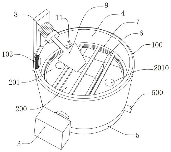
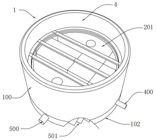
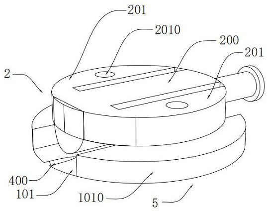
[0033] Such as Figure 1-8As shown, this embodiment provides a fryer, which includes a pot body 1, a heating liner 2 and a burner 3; wherein, the pot body 1 includes a pot wall 100, a partition 101 and a bottom plate 102; The pot wall 100 is a double-layer structure, and the interlayer is filled with an insulating layer 103; the bottom plate 102 is arranged on the lower end surface of the pot wall 100, the partition 101 is arranged in the inner cavity of the pot body 1, and the The inner cavity of the pot body 1 is divided into an upper frying chamber 4 and a lower heating chamber 5. The partition 101 is arranged obliquely. The exhaust pipe 500 is set; the slag discharge pipe 400 is set at the lowest position where the partition 101 is connected with the pot wall 100; the heating liner 2 is set in the frying chamber 4 and erected on the The partition plate 101, the inner cavity pipeline of the heating liner 2 communicates with the heating chamber 5; the burner 3 is arranged o...

Embodiment 2

[0040] In this embodiment, the partition plate 101 adopts a planar plate structure, which is not shown in the figure, and the rest of the structure is the same as in Embodiment 1, and will not be repeated here.

Embodiment 3

[0042] Such as Figure 9 As shown, the pot wall is a double-layer structure and an insulating layer is filled in the interlayer, and an oil overflow collection tank 12 is set in the upper end surface of the pot wall of the double-layer structure; an oil overflow collection pipe 13 is also included, and the oil overflow The collecting pipe 13 communicates with the outside of the overflow oil collection tank 12 and the pot wall 100; preferably in the present embodiment, a stepped groove is provided at the junction of the inner side wall of the pot wall 100 and the upper end surface as the oil overflow collection tank 12, and the pot wall The outer wall of the pot wall 100 constitutes the tank wall of the oil overflow collection tank 12, and the frying chamber 4 is directly connected with the oil overflow collection tank 12. When a large amount of foam generated by frying overflows the upper end surface of the inner wall of the pot wall 100, it will enter the stepped tank , and f...


PUM


Abstract

The invention discloses a fryer, which belongs to the field of food processing machinery, and particularly comprises a fryer body, a heating liner and a combustor. According to the design, on one hand, the high-temperature heating liner is suspended in an edible oil environment and performs efficient heat exchange with edible oil from the interior of the edible oil; on the other hand, high-temperature waste gas generated after combustion enters a heating chamber located on the lower portion along the pipeline, a partition plate is heated again in the heating chamber, the mode is similar to thetraditional mode that the pot bottom is heated below the pot body, that is, the pot body containing edible oil is heated again outside the edible oil, and the heat energy utilization rate is remarkably increased; besides, the heating liner is suspended in an edible oil environment, fried oil falls onto the partition plate, although the partition plate is heated again by high-temperature waste gas, the fried oil carbonization degree cannot be reached, and therefore the possibility that the fried oil is carbonized and blackened is eliminated, the service life of the edible oil is prolonged, andthe quality of the edible oil is stable.

Description

technical field [0001] The invention belongs to the field of food processing machinery, and in particular relates to a fryer for frying fried tofu. Background technique [0002] The frying of fried tofu is mainly completed in a deep fryer. This type of deep fryer on the market is mainly composed of a pot body, a high-temperature heat source arranged under the pot body, and a submerged sieve plate arranged in the pot. Its working process and principle are also More traditionally, the heat source is placed under the pot body, and the pot body can only absorb the heat transfer from the heat source in the upward direction, while the heat energy transferred to the side is wasted, the heating efficiency of the cooking oil in the pot is limited, and the heating rate is not high; [0003] In addition, during the frying process of fried tofu, a part of the oil residue is deposited on the bottom of the pot, while the other side of the pot body directly exchanges heat with the high-tem...

Claims


Application Information

Patent Timeline
Patent Type & Authority Applications(China)
IPC IPC(8): A21B5/08
CPCA21B5/08
Inventor 王海峰
Owner 浙江超太环保设备有限公司
Learn More