

Adjustable file storage cabinet
A storage cabinet, adjustable technology, applied in the field of shelves or shelf components, cabinets, can solve the problem of the position limitation of the card slot in the cabinet, so as to achieve the effect of easy support and improved applicability
- Summary
- Abstract
- Description
- Claims
- Application Information
AI Technical Summary
Problems solved by technology
Method used
Image

Examples
Embodiment 1
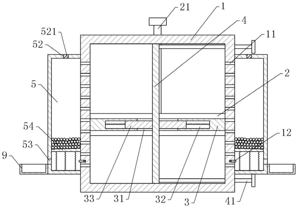
[0036] An adjustable file storage cabinet, basically as attached figure 1 Shown, comprise cabinet body 1, the front end opening of cabinet body 1, a cabinet door (not shown in the figure) is hinged respectively at the left and right ends of opening, can realize that cabinet body 1 is closed; Cabinet body 1 and cabinet door pass through Page hinges. The cabinet body 1 is also provided with a partition board, which includes a horizontal board 3 and a vertical board 4. The upper and lower inner walls of 1 are attached to each other.
[0037] The middle part of the horizontal plate 3 is provided with a through hole 31, and the horizontal plate 3 is also provided with a sliding groove 32 communicated with the left and right ends of the through hole 31. In the sliding groove 32, a supporting plate 33 is horizontally slidably connected, and the supporting plate 33 and the sliding Springs are arranged between the grooves 32, and in this embodiment, extension springs are used for the...
Embodiment 2
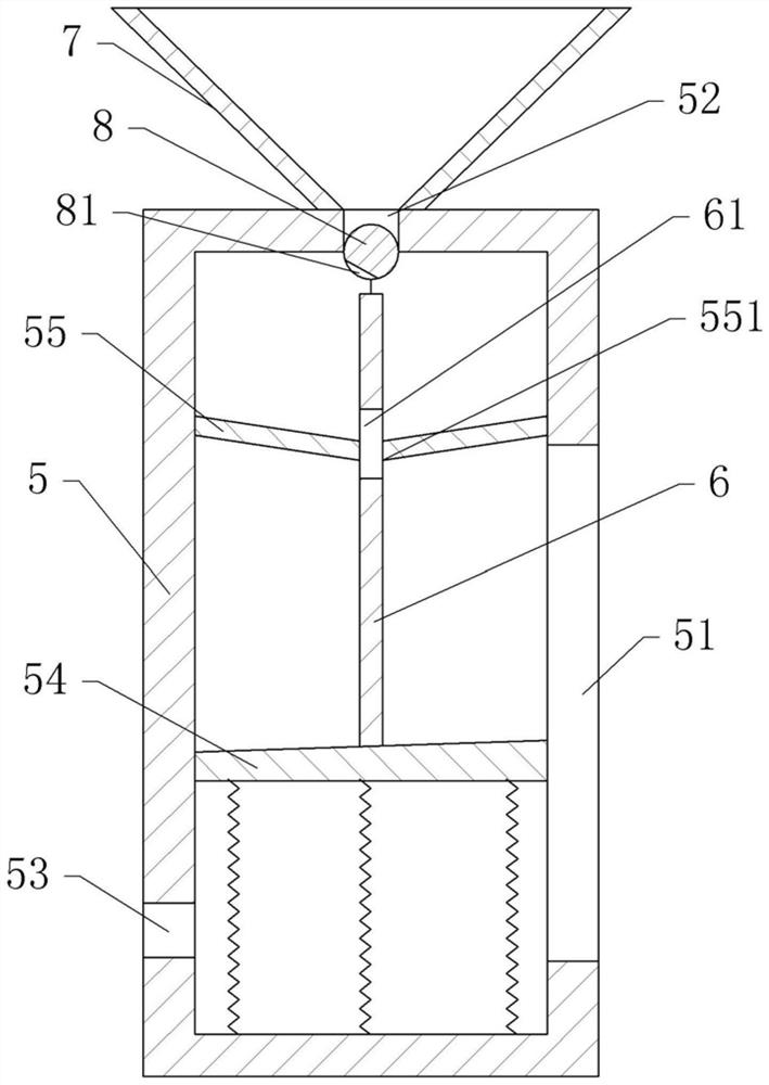
[0050] Embodiment 2 differs from Embodiment 1 only in that, as figure 2 As shown, the dehumidification unit in this embodiment also includes a feeding barrel 7, the feeding barrel 7 is conical, and the bottom of the feeding barrel 7 is open, the bottom of the feeding barrel 7 is inserted into the feeding port 52, and the feeding barrel 7 and the feeding port 52 Welding, therefore can realize that feeding barrel 7 communicates with dehumidification box 5. The top of the feeding barrel 7 is sealed, and the top of the feeding barrel 7 is provided with a feed inlet, and a sealing block is arranged in the feed inlet, and several molecular sieves are arranged in the feed barrel 7 .
[0051] Also be provided with rotating shaft 8 in the dehumidification box 5, the front and rear ends of the rotating shaft 8 are all coaxially fixed with rotating rods, and the rotating rods are rotatably connected on the front and rear side walls of the dehumidifying case 5. The upper part of the rot...
PUM
 Abstract
Description
Claims
Application Information