Oil mist pre-recovery device with compression structure and forced isolation function

A recovery device and oil mist technology, which is applied in the direction of combination device, separation method, and dispersed particle separation, can solve the problems of frequent replacement of consumables, pollution, poor filtration effect, etc., to reduce the cost of consumables and manpower for replacement of consumables, and to achieve high-efficiency filtration The effect of liquefaction collection and efficient recovery effect

Pending Publication Date: 2020-10-30
SHANDONG SHANSEN NUMERICAL CONTROL TECH CO LTD
View PDF0 Cites 0 Cited by
  • Summary
  • Abstract
  • Description
  • Claims
  • Application Information

AI Technical Summary

Problems solved by technology

[0002] When machine tool equipment is processing mechanical parts, auxiliary oil such as cutting fluid is sprayed on high-speed rotating equipment components, which will generate a large amount of water mist, oil mist and other mist due to high temperature and high speed, and directly discharge into the air will cause pollution
[0003] At present, most oil mist recovery devices with consumables use fan-shaped impellers for centrifugal or axial drive recovery. The airflow channel is unblocked. It belongs to the pre-filter straight-through structure, and the compression capacity is limited. The filtering effect is not good without consumables.
Relying on the built-in multi-layer filter consumables in the channel to achieve adsorption and recovery, the recovered oil accumulates in the filter consumables, which increases the burden on the filter consumables and shortens their life. The oil mist recovery device has no cooling treatment to improve the efficiency of oil mist liquefaction recovery

Method used


Image

  • Oil mist pre-recovery device with compression structure and forced isolation function
  • Oil mist pre-recovery device with compression structure and forced isolation function
  • Oil mist pre-recovery device with compression structure and forced isolation function

Examples


Embodiment

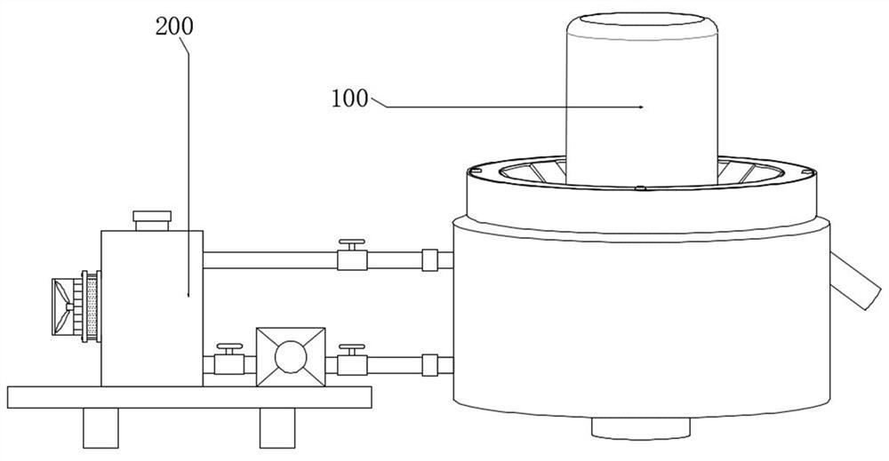
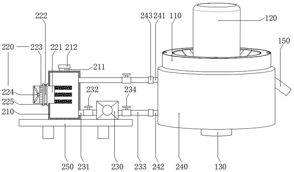
[0032] see Figure 1-3 , the present invention provides a technical solution: an oil mist pre-recovery device with a compression structure and forced isolation includes a liquefaction isolation mechanism 100 and a jacket water cooling mechanism 200 .

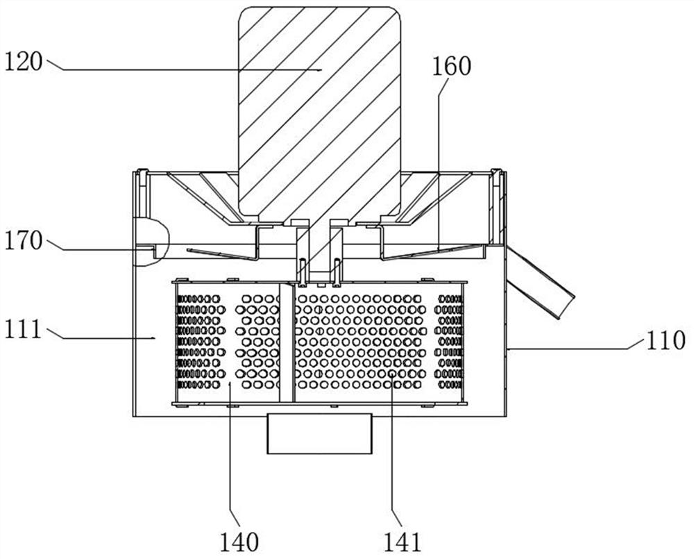
[0033] see figure 1 , figure 2 and image 3The liquefaction isolation mechanism 100 includes an oil mist channel housing 110, a motor 120, an air intake pipe 130, a porous impeller 140, an oil return pipe 150, an exhaust part 160 and a retaining ring 170, and the motor 120 is fixedly connected to the top of the oil mist channel housing 110, The motor 120 is screwed and fixedly connected to the top of the oil mist channel housing 110, the output end of the motor 120 is fixedly connected to the top of the porous impeller 140, the output end of the motor 120 is screwed and fixedly connected to the top of the porous impeller 140, and the porous impeller 140 is rotatably connected to the oil mist channel housing Inside 110, a liq...


PUM


Abstract

The invention provides an oil mist pre-recovery device with a compression structure and a forced isolation function, and belongs to the technical field of oil mist recovery. The oil mist pre-recoverydevice with the compression structure and the forced isolation function comprises a liquefaction isolation mechanism and a jacket water cooling mechanism, the liquefaction isolation mechanism comprises an oil mist channel shell, a motor, an air inlet pipe, a porous impeller, an oil return pipe, an exhaust part and a check ring, wherein the motor is fixedly connected to the top of the oil mist channel shell, the output end of the motor is fixedly connected with the top of the porous impeller, the porous impeller is rotatably connected to the interior of the oil mist channel shell, and the jacket water cooling mechanism comprises a water tank, a refrigerator, a water pump, a jacket pipe and a base. According to the device, the function of oil mist front efficient filtering, liquefying and collecting is achieved, no consumable is needed, the dependence of an oil mist recycling product on consumables is greatly reduced, the consumable cost and consumable replacement manpower are reduced, and the oil mist liquefying and recycling efficiency is improved.

Description

technical field [0001] The invention relates to the technical field of oil mist recovery, in particular to an oil mist pre-recovery device with a compression structure and forced isolation. Background technique [0002] When machine tool equipment is processing mechanical parts, cutting fluid and other auxiliary oils are sprayed on high-speed rotating equipment components. Affected by high temperature and high speed, a large amount of mist such as water mist and oil mist will be generated, and direct discharge into the air will cause pollution. [0003] At present, most oil mist recovery devices with consumables use fan-shaped impellers for centrifugal or axial drive recovery. The airflow channel is smooth. It belongs to the pre-filter straight-through structure, and the compression capacity is limited. The filtering effect is not good without consumables. Relying on the built-in multi-layer filter consumables in the channel to achieve adsorption and recovery, the recovered ...

Claims


Application Information

Patent Timeline
Patent Type & Authority Applications(China)
IPC IPC(8): B01D50/00
CPCB01D50/00
Inventor 杨德伟张启甲秦峰李光冉许西凡蒋雷何大伟张云法徐东崔建勋
Owner SHANDONG SHANSEN NUMERICAL CONTROL TECH CO LTD
Why Eureka
Try Eureka