Premixing device capable of mixing natural gas drag reducers step by step

A technology of drag reducing agent and natural gas, applied in mixer, transportation and packaging, dissolving and other directions, can solve the problems of inability to implement construction cost, lower inner coating and high cost

Inactive Publication Date: 2020-10-30
SINOPEC GUANGZHOU ENG +1
View PDF5 Cites 0 Cited by
  • Summary
  • Abstract
  • Description
  • Claims
  • Application Information

AI Technical Summary

Problems solved by technology

[0003] Pipeline inner coating drag reduction technology is generally used at home and abroad to reduce pipe wall roughness, but the construction equipment of pipeline inner coating drag reduction technology is complex and expensive, and the drag reduction effect gradually decreases or even decreases as time goes by due to the continuous peeling off of the inner coating. Produce negative effects, and at the same time, the original non-coated pipeline cannot be implemented due to construction costs and other issues

Method used


Image

  • Premixing device capable of mixing natural gas drag reducers step by step
  • Premixing device capable of mixing natural gas drag reducers step by step
  • Premixing device capable of mixing natural gas drag reducers step by step

Examples


Embodiment Construction

[0024] The structural layout, operation process and innovations of the present invention will be further described below in conjunction with the accompanying drawings and specific embodiments.

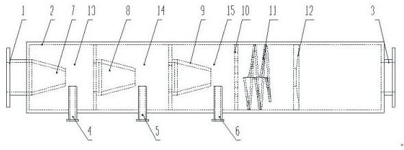
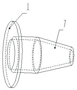
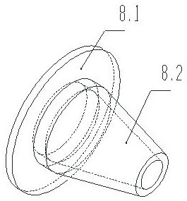
[0025] See attached Figure 1~6 , a kind of step-by-step blending natural gas drag reducer premixing device of the present invention, comprising a shell 2, the shell 2 is a long cylindrical structure, the natural gas inlet 1 is located at the center of one end of the shell 2, and the atomized drag reducer outlet 3 is located at The center of the other end of the housing 2; inside the housing 2, the first jet nozzle 7, the second jet nozzle 8, and the third jet nozzle are sequentially arranged along the axis of the housing from one end of the natural gas inlet 1 to the atomized drag reducer outlet 3. The nozzle 9 and the spiral blade 11, the natural gas inlet 1 is connected to the first jet nozzle 7, the first jet nozzle 7 extends into the space as the first mixing chamber 13, the secon...


PUM


Abstract

The invention discloses a premixing device capable of mixing natural gas drag reducers step by step. The premixing device comprises a shell, the shell is of a cylindrical structure. A natural gas inlet is formed in one end of the shell; an atomized drag reducer outlet is formed in the center of the other end of the shell; a first jet flow nozzle, a second jet flow nozzle, a third jet flow nozzle and a spiral blade are sequentially arranged in the shell from one end of the natural gas inlet along the axis of the shell; the natural gas inlet communicates with the first jet nozzle; a first drag reducer inlet pipe is centripetally arranged between the first jet flow spray head and the second jet flow spray head along the circumference of the shell, a second drag reducer inlet pipe is centripetally arranged between the second jet flow spray head and the third jet flow spray head along the circumference of the shell, and a third drag reducer inlet pipe is centripetally arranged between the third jet flow spray head and the spiral blade along the circumference of the shell. According to the invention, the natural gas and the drag reducer can be uniformly mixed through the mutual combination of step-by-step jet mixing, throttling, spiral flowing and the like.

Description

technical field [0001] The invention belongs to the technical field of gas-liquid mixing, in particular to a premixing device for gradually mixing natural gas drag reducer. Background technique [0002] For long-distance natural gas pipelines, the pressure loss of gas in the pipeline is an important issue. When the gas is in the turbulent region, especially the high Reynolds number region, due to the existence of turbulence and other irregular motions, the pressure loss caused by the gas energy loss is much larger, and the roughness of the tube wall is the main reason for the eddy flow. Therefore, reducing the pressure loss by reducing the roughness of the gas pipeline has become the main means to increase the gas flow. [0003] Pipeline inner coating drag reduction technology is generally used at home and abroad to reduce pipe wall roughness, but the construction equipment of pipeline inner coating drag reduction technology is complex and expensive, and the drag reduction ...

Claims


Application Information

Patent Timeline
IPC IPC(8): B01F13/10
CPCB01F33/8212
Inventor 王以斌郭维军丁梅峰杜富国
Owner SINOPEC GUANGZHOU ENG
Why Eureka
Try Eureka