Paint waste gas treatment device

A waste gas treatment device and waste gas treatment technology, applied in the direction of smoke removal, cleaning methods and appliances, chemical instruments and methods, etc., can solve problems such as inability to extract waste gas, pollute the environment, and waste gas leakage

Inactive Publication Date: 2020-10-30
鹤山市江磁线缆有限公司
View PDF7 Cites 0 Cited by
  • Summary
  • Abstract
  • Description
  • Claims
  • Application Information

AI Technical Summary

Problems solved by technology

[0006] However, in fact, the shield has a large space and cannot completely extract the exhau

Method used


Image

  • Paint waste gas treatment device
  • Paint waste gas treatment device

Examples


Embodiment Construction

[0025] This part will describe the specific embodiment of the present invention in detail, and the preferred embodiment of the present invention is shown in the accompanying drawings. Each technical feature and overall technical solution of the invention, but it should not be understood as a limitation on the protection scope of the present invention.

[0026] In the description of the present invention, it should be understood that the orientation descriptions, such as up, down, front, back, left, right, etc. indicated orientations or positional relationships are based on the orientations or positional relationships shown in the drawings, and are only In order to facilitate the description of the present invention and simplify the description, it does not indicate or imply that the device or element referred to must have a specific orientation, be constructed and operated in a specific orientation, and thus should not be construed as limiting the present invention.

[0027] I...


PUM


Abstract

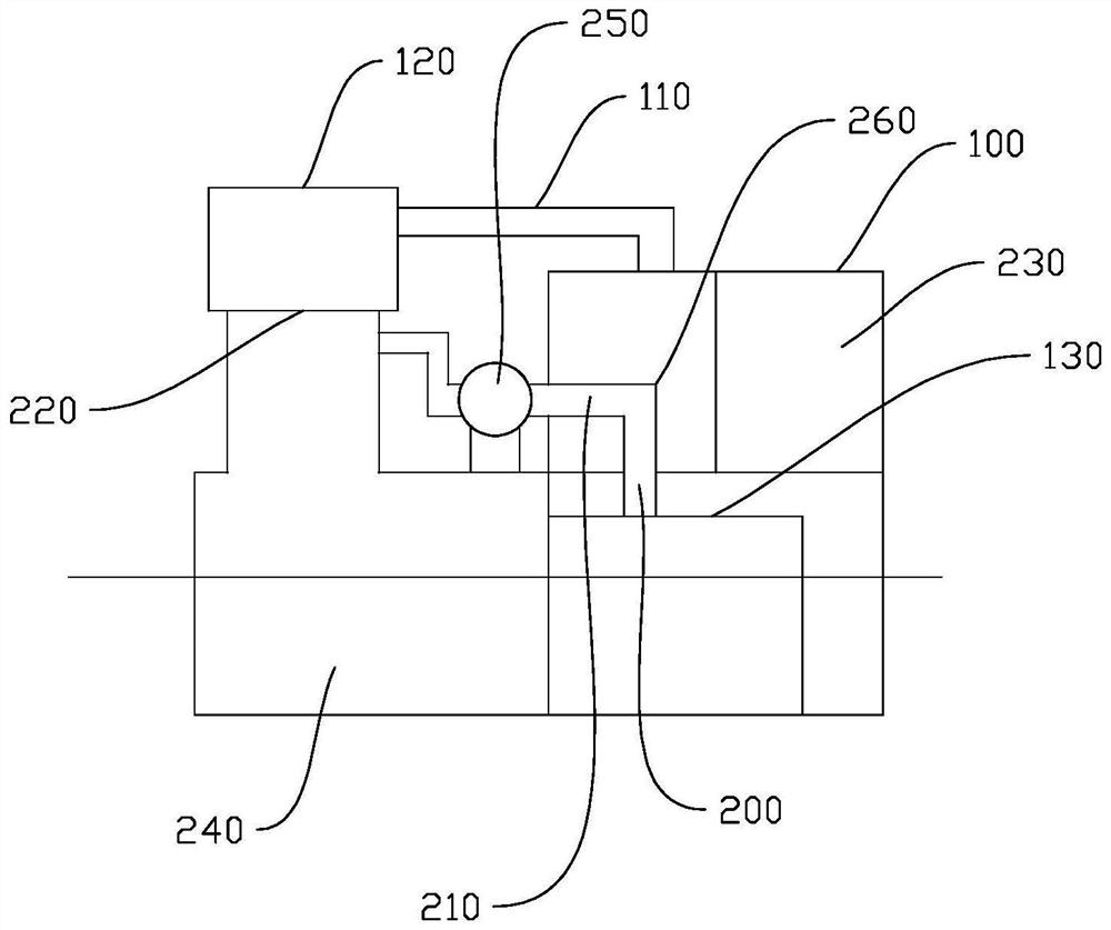
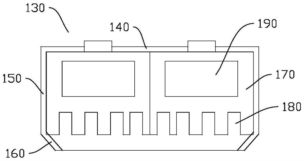
The invention discloses a paint waste gas treatment device. The paint waste gas treatment device comprises a waste gas treatment mechanism and an auxiliary exhaust mechanism. The waste gas treatment mechanism is provided with protective cover, a first air suction pipe and a treatment device, wherein the protective cover is arranged on a wire inlet side of a painting machine, the first air suctionpipe is connected to the top of the protective cover, and the treatment device is connected to the first air suction pipe. The auxiliary exhaust mechanism is provided with a cover body, a second air suction pipe and a fan, wherein the cover body is located in the protective cover, the second air suction pipe is connected to the cover body and penetrates through the protective cover, and the secondair suction pipe and the treatment device are connected through the first fan. With the paint waste gas treatment device, the capacity of removing waste gas by suction can be improved, less waste gasleaks out, and environmental pollution is reduced.

Description

technical field [0001] The invention relates to enameled wire production equipment, in particular to a paint waste gas treatment device. Background technique [0002] Enameled wire is a wire coated with insulating varnish on the surface. [0003] During production, the wires pass through a painting machine, are infiltrated by the paint of the painting machine, and then are dried to form enameled wires. [0004] In order to solve the problem of exhaust gas emitted by the paint machine, a shield, an exhaust pipe connected to the shield, and a processor connected to the exhaust pipe are provided on the wire entry side of the paint paint machine. [0005] Thus, the exhaust gas is drawn into the shroud first, and then the exhaust gas is introduced into the processor, thereby burning or decomposing the exhaust gas. [0006] However, in fact, the shield has a large space, and the exhaust gas cannot be completely drawn out. When the shield is opened, the exhaust gas will leak out ...

Claims


Application Information

Patent Timeline
IPC IPC(8): B08B15/04
CPCB08B15/04
Inventor 梁康焯黄秀芬李宏壮
Owner 鹤山市江磁线缆有限公司
Why Eureka
Try Eureka