
Milling fixture with waste recovery function

A waste recycling and functional technology, applied in the direction of clamping, manufacturing tools, supports, etc., can solve the problems of difficult dismantling, low work efficiency, and a large amount of waste iron filings, etc., and achieve the effect of reasonable structural design and improved functionality

Inactive Publication Date: 2021-04-30
张旨玉
View PDF10 Cites 0 Cited by
  • Summary
  • Abstract
  • Description
  • Claims
  • Application Information

AI Technical Summary

Problems solved by technology

[0003] However, the existing clamping tool is a fixed structure, which is not easy to dismantle when it is installed on the workbench on the bed. During the milling process, a large amount of waste iron filings will be generated. Band-shaped iron filings and granular iron filings are not easy to sort, and the work efficiency is low when waste is recycled and sorted.

Method used


Image

  • Milling fixture with waste recovery function
  • Milling fixture with waste recovery function
  • Milling fixture with waste recovery function

Examples


Embodiment Construction

[0033] The following is a clear and complete description of the technical solution of the patent of the present invention in conjunction with the accompanying drawings. Apparently, the described embodiments are part of the embodiments of the present invention, not all of them. Based on the embodiments of the present invention, all other embodiments obtained by those skilled in the art without creative efforts fall within the protection scope of the present invention.

[0034] In the description of the present invention, it should be noted that if the terms "center", "upper", "lower", "left", "right", "vertical", "horizontal", "inner", "outer" appear The orientation or positional relationship indicated by etc. is based on the orientation or positional relationship shown in the drawings, and is only for the convenience of describing the present invention and simplifying the description, rather than indicating or implying that the referred device or element must have a specific or...


PUM


Abstract

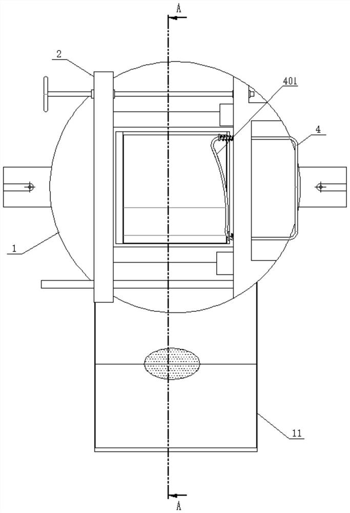
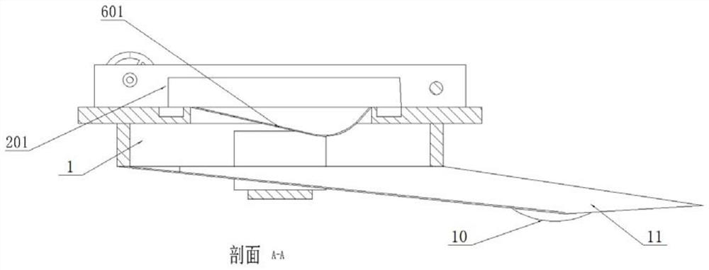
The invention provides a milling clamp with a waste recycling function. The milling clamp with the waste recycling function comprises a base and a fixing base, a welding seat is fixed to the left side of the top face of the base, a sliding rail is arranged on the right side of the top face of the base, a clamping base is installed through the sliding rail, the clamping base and the welding seat are in driving connection through a guide column and a screw rod, a clamping structure used for clamping and placing a workpiece is formed, a blanking groove is formed in the middle of the base, the middle of a discharging hopper is designed to be bent, a liquid collecting bin is arranged at the bottom of a bent section, a material opening is formed in the bottom of the welding seat, granular scrap iron is leaked and discharged, and a filter bin is arranged, so that waste materials produced in the milling process are classified and collected, and the filter bin is connected into the blanking groove through a left row of spring seats and a right row of spring seats; when a workpiece is milled by a milling cutter, vibration is generated, the vibration effect acts on the filter cabin, so that the filter cabin vibrates, waste materials flowing into the filter cabin during milling are sieved, and granular waste materials can fall to the bottom and are directly discharged during sieving.

Description

technical field [0001] The invention relates to the technical field of fixtures, in particular to a milling fixture with the function of recycling waste materials. Background technique [0002] Milling is a mechanical processing method in which a milling cutter is used as a tool to process the surface of an object. Milling machines include horizontal milling machines, vertical milling machines, gantry milling machines, profiling milling machines, universal milling machines, and bar milling machines. The tool, the tool magazine, and the tool feed control system are composed of a working platform on the bed, and a clamping tool for clamping the workpiece is provided on the platform. [0003] However, the existing clamping tool is a fixed structure, which is not easy to dismantle when it is installed on the workbench on the bed. During the milling process, a large amount of waste iron filings will be generated. Band-shaped iron filings and granular iron filings are not easy t...

Claims


Application Information

Patent Timeline
Patent Type & Authority Applications(China)
IPC IPC(8): B23Q3/06B23Q11/00B01D29/03
CPCB23Q3/06B23Q11/0042B01D29/03Y02P70/10
Inventor 张旨玉
Owner 张旨玉
Learn More