
Permeable reactive barrier, box structure and reactive barrier implementation method

A technology of osmotic reaction wall and box structure, which is applied in the direction of basic structure engineering, walls, building components, etc., and can solve problems such as incomplete pollution control, inability to realize restoration of complex geological conditions, secondary pollution, etc.

Active Publication Date: 2020-10-30
SINOHYDRO FOUND ENG
View PDF6 Cites 0 Cited by
  • Summary
  • Abstract
  • Description
  • Claims
  • Application Information

AI Technical Summary

Problems solved by technology

[0003] Currently publicly available practices on groundwater permeable reactive walls are all focused on the treatment of shallow groundwater on the surface, and cannot achieve complex geological conditions, contaminated groundwater, or deep soil restoration; moreover, general-purpose groundwater permeable reactive walls will The repair function of the groundwater reaction wall is passivated and the repair efficiency becomes poor. In this case, there must be the problem of incomplete pollution control; in addition, the replacement of the reaction medium in the infiltration reaction wall basically requires reinstallation of the reaction wall system. Large excavation method makes it difficult to standardize the repair medium, which leads to the problem of secondary pollution, and this shortcoming greatly restricts the promotion and use of groundwater permeable reaction walls

Method used


Image

  • Permeable reactive barrier, box structure and reactive barrier implementation method
  • Permeable reactive barrier, box structure and reactive barrier implementation method
  • Permeable reactive barrier, box structure and reactive barrier implementation method

Examples


Embodiment Construction

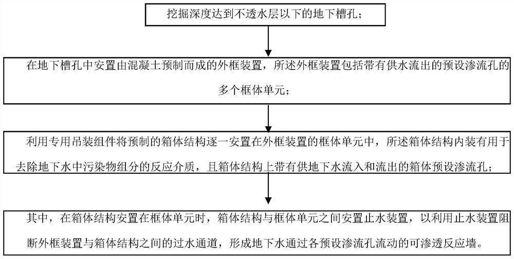
[0076] like figure 1 As shown, it is a flow chart of a method for realizing a permeable reaction wall provided by the present invention. As can be seen from the figure, the method includes:

[0077] Dig underground slots below the impermeable layer;

[0078] An outer frame device prefabricated by concrete is arranged in the underground slot, and the outer frame device includes a plurality of frame body units with preset seepage holes for water supply to flow out;

[0079] The prefabricated box structures are placed in the frame units of the outer frame device one by one using special hoisting components. The box structure contains a reaction medium for removing pollutant components in groundwater, and the box structure is provided with groundwater for inflow. and preset seepage holes in the outflow box;

[0080] Wherein, when the box body structure is placed in the frame body unit, a water stop device is also arranged between the box body structure and the frame body unit, s...


PUM


Abstract

The invention discloses a box structure of a permeable reactive barrier, the permeable reactive barrier and an implementation method. The method comprises the following steps that: an underground slotted hole is excavated; an outer frame device is arranged in the underground slotted hole, wherein the outer frame device comprises a plurality of frame body units with preset seepage holes for water to flow out; the box body structure is arranged in the frame body unit through a special hoisting assembly, a reaction medium used for removing pollutant components in underground water is contained inthe box body structure, and preset seepage holes allowing the underground water to flow in and flow out are formed in the box body structure; when the box body structure is arranged in the frame bodyunit, a water stopping device is arranged between the box body structure and the frame body unit, so that a water passing channel between the box body structure and the frame body unit is blocked bythe water stopping device, and underground water flows through the preset seepage holes. By means of the method, the underground water permeable reactive barrier can be constructed under complex stratum conditions or at deep positions, underwater stacking can be achieved through the box body structure, and the box body structure can be repeatedly used and is easy to replace, more environmentally friendly in treatment and low in cost.

Description

technical field [0001] The invention relates to the field of groundwater and soil pollution remediation and treatment for environmental treatment, in particular to a box structure of a permeable reaction wall, a permeable reaction wall and a realization method thereof. Background technique [0002] The groundwater permeable reaction wall is an in-situ treatment system for the remediation of groundwater and soil pollution. A series of physical, chemical or biological actions such as adsorption and adsorption are used to achieve groundwater remediation to achieve certain discharge targets. It is an in-situ remediation method that uses natural or artificial groundwater hydraulic gradients. [0003] At present, the publicly visible methods of groundwater permeable reaction walls focus on the treatment of shallow groundwater on the surface, and cannot achieve complex geological conditions, contaminated groundwater or deep soil restoration; moreover, general groundwater permeable ...

Claims


Application Information

Patent Timeline
Patent Type & Authority Applications(China)
IPC IPC(8): B09C1/00E04B2/00E02D31/00
CPCB09C1/002E04B2/00E02D31/00
Inventor 徐方才孙亮杨晓蓉江志安白雪翁嘉玲赵明华苗志斌胡微李云松刘健
Owner SINOHYDRO FOUND ENG
Learn More