High-frequency plasma cutting gun

A high-frequency plasma and cutting torch technology, which is applied in plasma welding equipment, welding equipment, metal processing equipment, etc., can solve the problems of multiple parts, increased manufacturing cost, scrapped torch head, etc., to reduce high temperature, improve life, and prolong use The effect of longevity

Pending Publication Date: 2020-10-30
无锡汉特机电有限公司
View PDF0 Cites 1 Cited by
  • Summary
  • Abstract
  • Description
  • Claims
  • Application Information

AI Technical Summary

Problems solved by technology

[0002] The existing high-frequency plasma gun head has many shortcomings in production: the shape of the gun head is complicated, the parts are numerous, the manufacturing cost is high, and some parts are damaged and cannot be repaired.
[0003] 1) The molding of the gun head is complicated: the molding of the gun head needs to use a special injection molding machine for the injection molding operation, and the injection molding body is formed to make the gun head shape and insulate. high cost;
[0004] 2) Parts cannot be replaced, and the damage rate is high: the insulator is pressed into the inside of the gun head, and is bonded to the surrounding metal parts through injection molding. If the damage cannot be replaced, the entire gun head will be scrapped;
[0005] 3) Many parts and high manufacturing cost: The joints at the end of the air pipe are complex and numerous. After the rolling process is used for assembly, threaded joints are additionally screwed in, resulting in too many tail joints, multiple joints, and multiple parts, which increases the manufacturing cost, and The structure tends to be complex, increasing the risk of air leakage

Method used


Image

  • High-frequency plasma cutting gun
  • High-frequency plasma cutting gun

Examples


Embodiment Construction

[0027] The following will clearly and completely describe the technical solutions in the embodiments of the present invention. Obviously, the described embodiments are only some of the embodiments of the present invention, rather than all the embodiments. Based on the embodiments of the present invention, all other embodiments obtained by persons of ordinary skill in the art without making creative efforts belong to the protection scope of the present invention.

[0028] see Figure 1 to Figure 2 , the embodiment of the present invention includes:

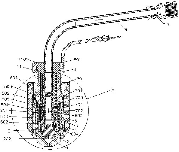
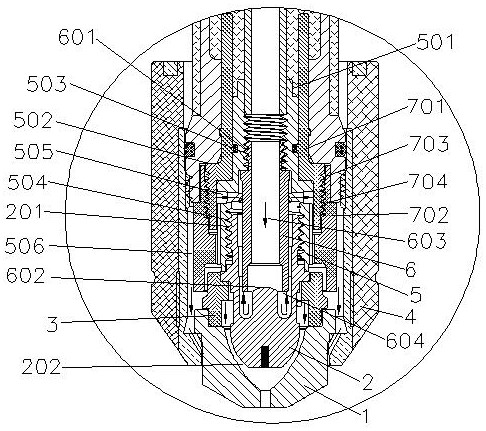
[0029] A high-frequency plasma cutting gun, comprising: a gun head body, the gun head body includes a large inner diameter cylindrical structure 11, the cavity of the large inner diameter cylindrical structure 11 is sequentially equipped with an injection molding body 8, an insulator 7, a shunt 5, a guide Flow tube 6, electrode 2 and cutting nozzle 1.

[0030] The main body of the gun head also includes a gas pipe 9, which is ins...


PUM


Abstract

The invention discloses a high-frequency plasma cutting gun. An injection molded body, an insulator, a diverter, a diversion tube, an electrode and a cutting nozzle are arranged inside a large inner diameter cylindrical structure of a gun head body, the injection molded body is matched with the large inner diameter cylindrical structure in a standstill locking mode, a diverter boss is inserted into the injection molded body, the diversion tube is installed in an inner cavity of the diverter, a diversion cavity is arranged inside the diversion tube, the electrode is arranged outside the diversion tube, an annular airflow gap is arranged between the electrode and the diversion tube, a first diversion channel is arranged on the diverter, the first diversion channel is communicated with the inner cavity of the diverter, a second diversion channel is arranged between the insulator and a protective cap, the cutting nozzle is connected to the bottom of the electrode, a vortex ring is arrangedbetween the cutting nozzle and the diverter, vortex holes are formed in the surface of the vortex ring, and a plasma arc gap is arranged between the electrode and the cutting nozzle. The high-frequency plasma cutting gun has the characteristics of anti-falling-out and anti-rotation, a gun head can be replaced, airflow fully flows back to the gun head everywhere in a surrounding mode, the high temperature of the gun head and consumables is effectively reduced, and the service life is prolonged.

Description

technical field [0001] The invention relates to the field of welding technology, in particular to a high-frequency plasma cutting gun. Background technique [0002] The existing high-frequency plasma torch head has many deficiencies in production and production: the torch head has complicated molding, many parts, high manufacturing cost, and some parts are damaged and cannot be repaired. [0003] 1) The molding of the gun head is complicated: the molding of the gun head needs to use a special injection molding machine for the injection molding operation, and the injection molding body is formed to make the gun head shape and insulate. high cost; [0004] 2) Parts cannot be replaced, and the damage rate is high: the insulator is pressed into the inside of the gun head, and is bonded to the surrounding metal parts through injection molding. If the damage cannot be replaced, the entire gun head will be scrapped; [0005] 3) Many parts and high manufacturing cost: The joints a...

Claims


Application Information

Patent Timeline
Patent Type & Authority Applications(China)
IPC IPC(8): B23K10/00
CPCB23K10/00
Inventor 周志需朱雪峰
Owner 无锡汉特机电有限公司
Why Eureka
Try Eureka