Clamping device for thin-wall sleeve

A technology of clamping device and thin-wall sleeve, which is applied in the direction of positioning device, clamping, support, etc., can solve the problems of thin-wall sleeve deformation under force, weak strength, easy deformation, etc., so as to improve installation efficiency, facilitate installation, The effect of preventing follow-up

Inactive Publication Date: 2020-10-30
南京江宁区上峰国银标准件厂
View PDF8 Cites 4 Cited by
  • Summary
  • Abstract
  • Description
  • Claims
  • Application Information

AI Technical Summary

Problems solved by technology

[0003] However, the processing of thin-walled parts is a difficult problem in turning. The reason is that thin-walled parts have poor rigidity and weak strength, and are easily deformed during processing, which increases the shape and position error of the parts and makes it difficult to guarantee the processing quality of the parts.
[0004] The existing end face processing for thin-walled sleeves is more difficult for ordinary cars, mainly because it is difficult to control the clamping force of the thin-walled sleeves, which makes the thin-walled sleeves deform under force, resulting in machining The product that comes out is not ideal

Method used


Image

  • Clamping device for thin-wall sleeve
  • Clamping device for thin-wall sleeve
  • Clamping device for thin-wall sleeve

Examples


Embodiment Construction

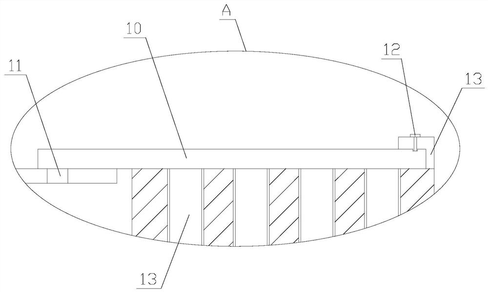
[0028] The present invention is described in further detail now in conjunction with accompanying drawing. These drawings are all simplified schematic diagrams, which only illustrate the basic structure of the present invention in a schematic manner, so they only show the configurations related to the present invention.

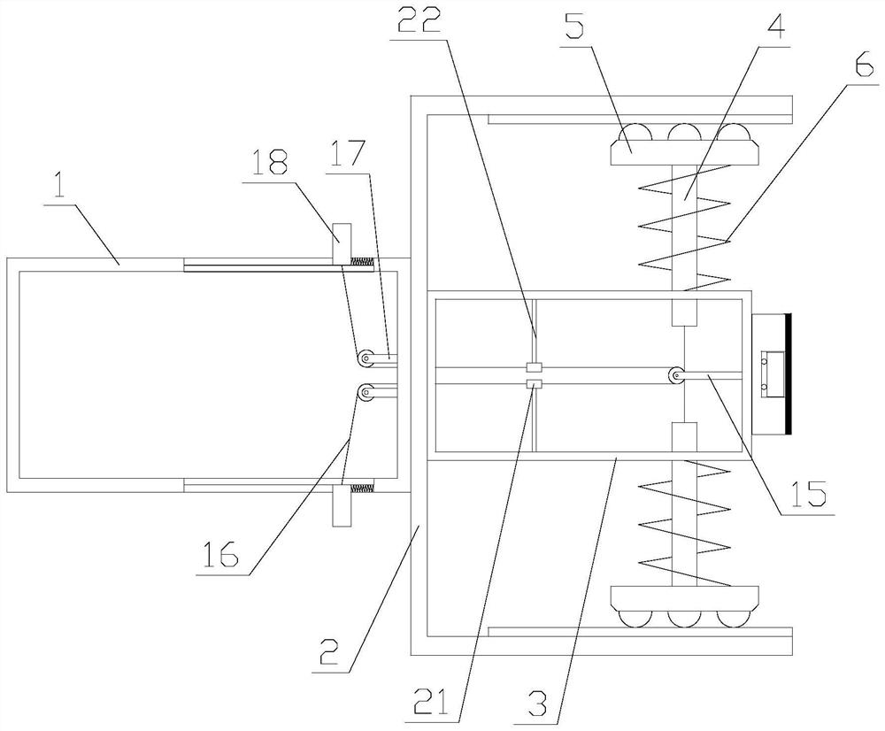
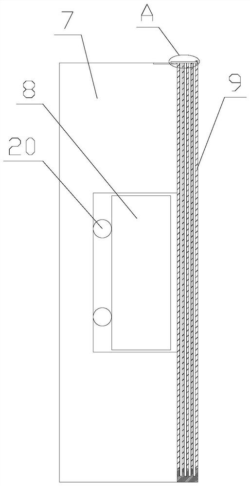
[0029] Such as Figure 1-5 As shown, a clamping device for a thin-walled sleeve includes a fixed rod 1, a circular plate 2, a connecting rod 3, a clamping mechanism and a driving mechanism. The fixed rod 1 is set horizontally, and the circular plate 2 is set On one side of the fixed rod 1, the circular plate 2 is hollowly arranged, the end of the circular plate 2 away from the fixed rod 1 is provided with an opening, the connecting rod 3 is horizontally arranged in the circular plate 2, and the connecting rod 3 One end is connected with the end of the circular plate 2 close to the fixed rod 1, the clamping mechanism is arranged in the circular plate 2, the co...


PUM

PropertyMeasurementUnit
thicknessaaaaaaaaaa

Abstract

The invention relates to a clamping device for a thin-wall sleeve. The clamping device comprises a fixed rod, a round plate, a connecting rod, a clamping mechanism and a driving mechanism. The clamping mechanism comprises a clamping assembly and a limiting assembly. The driving mechanism comprises a first fixed pulley and a driving assembly. According to the clamping device for the thin-wall sleeve, the thin-wall sleeve is fixed through the clamping mechanism, elastic clamping of clamping plates on the outer ring of the thin-wall sleeve is achieved through the restoring force of a first spring, and the situation that due to the fact that the clamping force is too large, the thin-wall sleeve deforms is avoided; meanwhile, the friction force of the clamping device and the thin-wall sleeve isincreased through a rubber pad and protrusions, and the thin-wall sleeve is prevented from rotating accordingly during end face machining; the end face in the thin-wall sleeve is fixed through a magnet, and therefore dual fixing on the thin-wall sleeve is achieved; and meanwhile, the magnitude of the magnetic force of the magnet is adjusted through an adjusting unit, the situation that due to thefact that the magnetic force is too large, the thin-wall sleeve deforms is avoided, the clamping assembly is controlled through the driving mechanism, and therefore the thin-wall sleeve is mounted more conveniently, and the mounting efficiency is improved.

Description

technical field [0001] The invention relates in particular to a clamping device for thin-walled sleeves. Background technique [0002] Thin-walled parts are metal parts with a wall thickness of less than 1mm. Thin-walled parts have been widely used in various industrial sectors because of their light weight, material saving, and compact structure. [0003] However, the processing of thin-walled parts is a difficult problem in turning. The reason is that thin-walled parts have poor rigidity and weak strength. [0004] The existing end face processing for thin-walled sleeves is more difficult for ordinary cars, mainly because it is difficult to control the clamping force of the thin-walled sleeves, which makes the thin-walled sleeves deform under force, resulting in machining The product that comes out is not ideal. Contents of the invention [0005] The technical problem to be solved by the present invention is to provide a clamping device for a thin-walled sleeve in orde...

Claims


Application Information

Patent Timeline
Patent Type & Authority Applications(China)
IPC IPC(8): B23Q3/12B23Q3/154
CPCB23Q3/12B23Q3/154
Inventor 韩平
Owner 南京江宁区上峰国银标准件厂
Why Eureka
Try Eureka