
Fixing fixture for machining

A fixed fixture and machining technology, applied in the field of fixed fixtures for machining, can solve problems such as poor workpiece clamping effect, and achieve the effects of improving clamping effect, facilitating uniform rotation and improving stability

Pending Publication Date: 2020-10-30
NANJING ZHIJIN TECH INNOVATION SERVICE CENT
View PDF0 Cites 3 Cited by
  • Summary
  • Abstract
  • Description
  • Claims
  • Application Information

AI Technical Summary

Problems solved by technology

[0005] The invention provides a fixed fixture for machining with good clamping effect, which solves the problem that the traditional fixture for machining has poor clamping effect on workpieces

Method used


Image

  • Fixing fixture for machining
  • Fixing fixture for machining
  • Fixing fixture for machining

Examples


Embodiment Construction

[0027] The present invention will be further described below in conjunction with the accompanying drawings and embodiments.

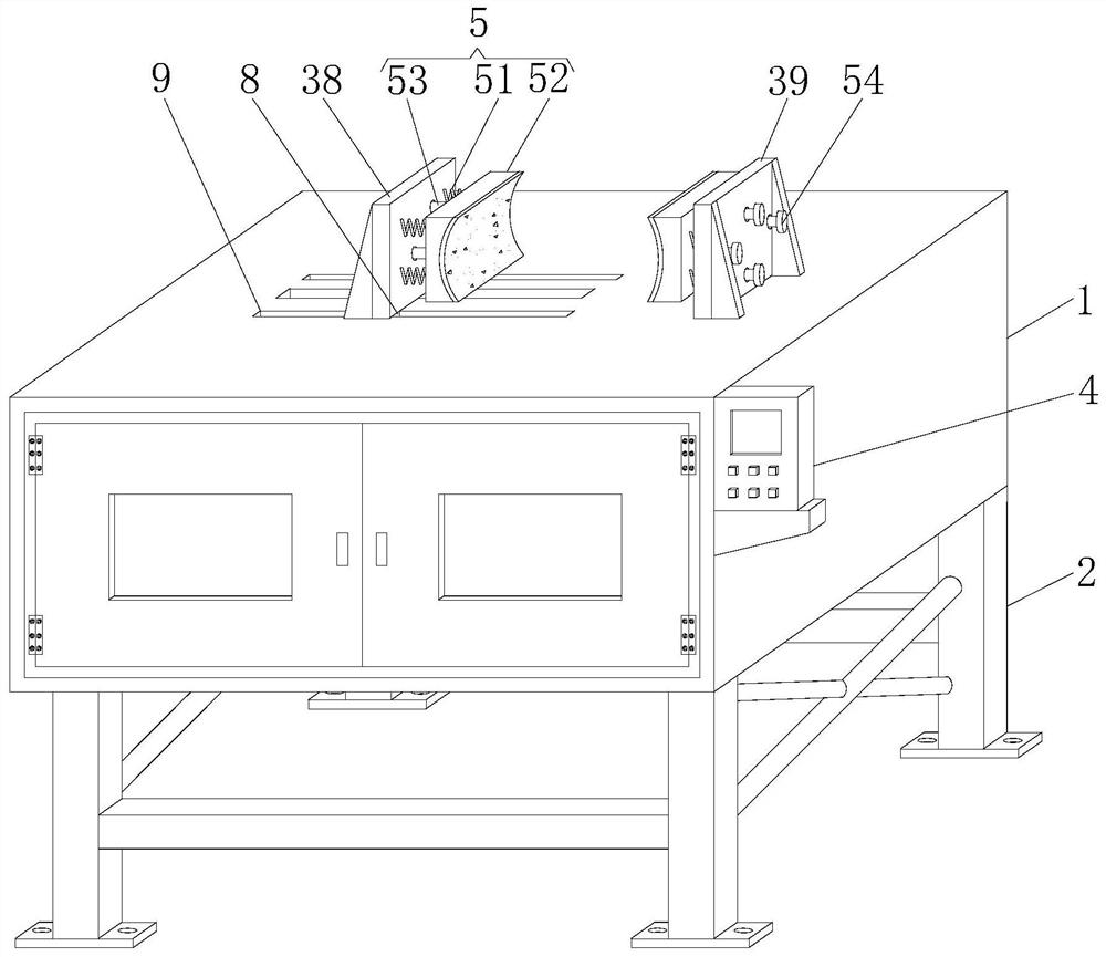
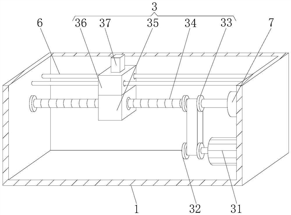
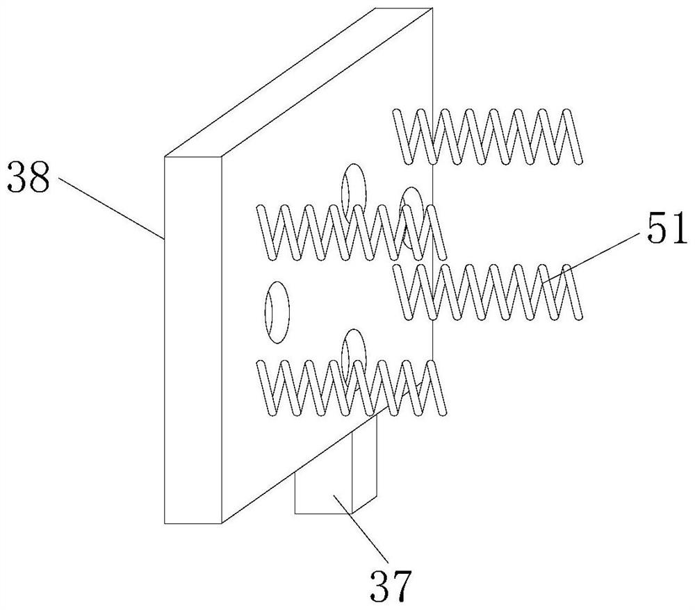
[0028] Please refer to figure 1 , figure 2 , image 3 , Figure 4 , Figure 5 and Image 6 ,in figure 1 A structural schematic diagram of a preferred embodiment of a fixture for machining with good clamping effect provided by the present invention; figure 2 for figure 1 The partial cross-sectional view of the structure of the fixed box shown; image 3 for figure 1 The structural perspective view of the moving column, moving plate and spring shown; Figure 4 for figure 1 The three-dimensional view of the structure of the clamping seat and the limit column shown; Figure 5 for figure 1 The perspective view of the structure of the screw rod, reducer and driven wheel shown; Image 6 for figure 1 The perspective view of the structure of the threaded sleeve, the moving block and the moving column is shown. A kind of fixing fixture for machini...


PUM


Abstract

The invention provides a fixing fixture for machining. The fixture comprises a fixing box, wherein support legs are connected around the bottom of the fixing box through bolts, a clamping mechanism isarranged in an inner cavity of the fixing box, a through groove is transversely formed in the left side of the top of the fixing box, the top of the clamping mechanism penetrates through the throughgroove and extends upwards, and fastening mechanisms are arranged at the tops of the opposite sides of the clamping mechanism. According to the fixture, through the cooperation of a motor, a driving wheel, a driven wheel, a screw rod, a threaded sleeve, a moving block, a moving column, a moving plate and a fixing plate, the moving plate is convenient to move by a user through using the motor, so that a clamping seat is driven to move inwardly, quick clamping limit of a workpiece is carried out, and the clamping effect of the fixing fixture is improved; and at the same time, through the cooperation of a spring, the clamping seat, a limit column and a limit block, secondary clamping limit of the workpiece is conveniently carried out by the user through elastic rebound of the spring.

Description

technical field [0001] The invention relates to the field of machining, in particular to a fixing fixture for machining with good clamping effect. Background technique [0002] Machining refers to the process of changing the shape or performance of a workpiece through a mechanical device. According to the difference in processing methods, it can be divided into cutting processing and pressure processing. The production process of a machine refers to the entire process of making products from raw materials. , For machine production, it includes transportation and storage of raw materials, production preparation, blank manufacturing, parts processing and heat treatment, product assembly, debugging, painting and packaging, etc. The content of the production process is very extensive. [0003] In the process of machining, it is necessary to use a fixed fixture to fix and clamp the workpiece to prevent the workpiece from shifting during the machining process, thereby affecting th...

Claims


Application Information

Patent Timeline
Patent Type & Authority Applications(China)
IPC IPC(8): B25B11/00
CPCB25B11/00
Inventor 高青赵金玲高岩
Owner NANJING ZHIJIN TECH INNOVATION SERVICE CENT
Learn More