
Machine tool panel operation manipulator based on circumferential motion

A machine tool panel, circumferential motion technology, applied in the directions of manipulators, metal processing mechanical parts, large fixed members, etc., can solve problems such as low transmission efficiency, inability to provide accurate force control, and complex transmission.

Active Publication Date: 2020-10-30
HARBIN ENG UNIV
View PDF3 Cites 0 Cited by
  • Summary
  • Abstract
  • Description
  • Claims
  • Application Information

AI Technical Summary

Problems solved by technology

At the same time, the existing manipulators have complex transmission, low transmission efficiency, poor reliability and cannot accurately provide force control

Method used


Image

  • Machine tool panel operation manipulator based on circumferential motion
  • Machine tool panel operation manipulator based on circumferential motion
  • Machine tool panel operation manipulator based on circumferential motion

Examples


Embodiment Construction

[0027] The present invention will be described in detail below with the best embodiment.

[0028] A machine tool panel operating manipulator based on circumferential motion, characterized in that:

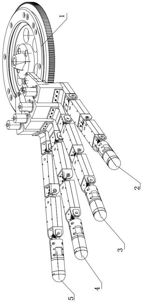
[0029] Such as figure 1As shown, the device is composed of a main body module, a first finger module, a second finger module, a third finger module and a fourth finger module. The 2-first finger module and the 1-body module are driven by gears, so that the 2-first finger module can perform circular motion around the 1-body module. The 3-second finger module and the 1-body module are driven by gears, so that the 3-second finger module can move around the 1-body module without colliding with the 2-first finger module. The 4-third finger module and the 1-body module are driven by gears, so that the 4-third finger module can go around the 1-body without colliding with the 2-first finger module and 3-second finger module The module makes a circular motion. The 5-fourth finger module...


PUM


Abstract

The invention discloses a machine tool panel operation manipulator based on circumferential motion, and relates to a manipulator structure, in particular to a manipulator structure capable of being applied to machine tool panel operation. The machine tool panel operation manipulator comprises a main body module and finger modules; and one or at least two finger modules are arranged on the periphery of the main body module and are in transmission with the main body module through a gear, and the four finger modules are non-collision. The manipulator can stably grab various objects by adjustingpositions of fingers and grasping and holding postures of the fingers. Meanwhile, contact operation such as key operation of a keyboard can be realized without cooperation of a mechanical arm, and adaptability of the manipulator is greatly improved.

Description

technical field [0001] The invention relates to a manipulator structure, in particular to a manipulator structure that can be used for machine tool panel operations. Background technique [0002] In our daily life and study, hands are very important to us. In industrial production, the end effector of the robotic arm is also the key to the correct execution of tasks. With the development of society and the advancement of science and technology, the existing end of the mechanical arm can no longer meet the needs of people in actual production and life. The end effector needs to be designed according to the operating object, so the designed end is often single-function and not universal. In addition, the existing wrist-palm mechanism whose end connects the gripper and the mechanical arm is fixed. Therefore, when the robotic arm is performing a variety of different operation objects, the end needs to be replaced frequently, which greatly affects the work efficiency. Moreove...

Claims


Application Information

Patent Timeline
Patent Type & Authority Applications(China)
IPC IPC(8): B25J15/00B23Q1/00
CPCB25J15/0009B23Q1/0045
Inventor 刘军张宏远
Owner HARBIN ENG UNIV
Learn More