
Veneer roller tooth joint machine and splicing process thereof

A technology of veneer and roller, which is applied in the jointing of wooden veneers, manufacturing tools, wood processing equipment, etc., can solve the problems of large veneer walking error, short cooling time of pressing mechanism, and long conveying distance of rollers, etc. Butt tooth joint and continuous tooth joint, improve the level of production automation, and the effect of uniform splicing gap

Pending Publication Date: 2020-10-30
山东昶兴智能科技有限公司
View PDF0 Cites 0 Cited by
  • Summary
  • Abstract
  • Description
  • Claims
  • Application Information

AI Technical Summary

Problems solved by technology

[0002] At present, in the production process of multi-layer plywood products, vertical veneers are used as raw materials necessary for the mechanical structure of plywood. Due to the influence of fast-growing forest wood diameter and material utilization rate, it is impossible to produce a complete vertical veneer that meets the size requirements of plywood. ; The existing vertical veneer butt joint equipment has a butt splicing machine and a continuous splicing machine, both of which have a single production function. The splicing machine can only perform continuous splicing, and the functional advantages of the butt splicing machine and the continuous splicing machine cannot be integrated. Plywood companies often need two pieces of equipment, each doing its own thing to meet the production of vertical veneers demand, which virtually increases production costs, seriously affects the process of plywood production automation, and restricts the development of plywood enterprises and the improvement of product quality
[0003] Disadvantages of the existing roller gear jointing machines on the market: Usually, the position of the veneer tooth joint is set in front of the sizing mechanism, which makes the roller conveying distance longer, and the roller is easy to stick glue, resulting in a large veneer walking error, and the cooling time of the pressing mechanism Short, no docking correction function, which affects the docking quality, and the cumulative docking error is very poor for continuous splicing

Method used


Image

  • Veneer roller tooth joint machine and splicing process thereof
  • Veneer roller tooth joint machine and splicing process thereof
  • Veneer roller tooth joint machine and splicing process thereof

Examples


Embodiment Construction

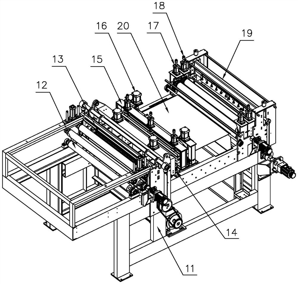
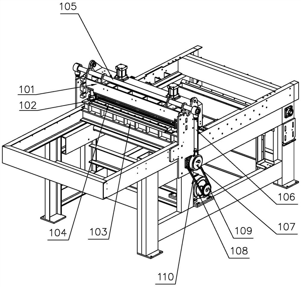
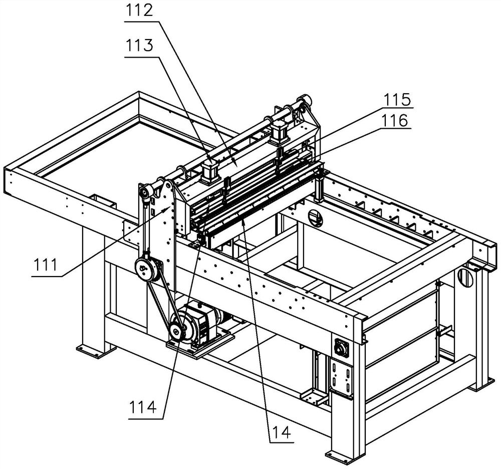
[0051] For the convenience of those skilled in the art to understand, the following in conjunction with the attached Figure 1-8 , to further specifically describe the technical solution of the present invention.

[0052] A veneer roller splicing machine, comprising a frame 11, a feeding mechanism 12, a comb mechanism 13, a gluing mechanism 14, a pressing mechanism 15, a front transmission docking adjustment mechanism 16, a feeding roller mechanism 17, a length-setting mechanism 19, Transfer mechanism 21; the upper part of the frame 11 is sequentially provided with a feeding mechanism 12, a comb mechanism 13, a gluing mechanism 14, a transfer mechanism 21, a feeding roller mechanism 17, a length-setting mechanism 19, a feeding mechanism 12, and a comb mechanism 13 , gluing mechanism 14, feeding roller mechanism 17, and length-setting mechanism 19 are fixedly connected on the frame 11, and the transfer mechanism 21 is movably connected with respect to the frame 11. Mechanism 1...


PUM


Abstract

The invention discloses a veneer roller tooth joint machine which comprises a rack, a feeding mechanism, a broaching mechanism, a gluing mechanism, a pressing mechanism, a front conveying butt-joint adjusting mechanism, a feeding roller mechanism, a roller rear conveying mechanism, a sizing mechanism and a transfer mechanism. The feeding mechanism, the broaching mechanism, the gluing mechanism, the transfer mechanism, the feeding roller mechanism, the roller rear conveying mechanism and the sizing mechanism are sequentially arranged on the upper portion of the rack. The feeding mechanism, thebroaching mechanism, the gluing mechanism, the feeding roller mechanism, the roller rear conveying mechanism and the sizing mechanism are fixedly connected to the rack. The transfer mechanism is movably connected relative to the rack. The pressing mechanism and the front conveying butt-joint adjusting mechanism are sequentially arranged on the upper portion of the transfer mechanism. Through action connection between the mechanisms, splicing gaps can be uniform, strength can be high, butt joint tooth joint and continuous tooth joint of vertical veneer can be met, and the automation level of plywood production is improved.

Description

technical field [0001] The invention belongs to the technical field of sheet material production equipment, and in particular relates to a veneer roller tooth splicing machine and a splicing process thereof. Background technique [0002] At present, in the production process of multi-layer plywood products, vertical veneers are used as raw materials necessary for the mechanical structure of plywood. Due to the influence of fast-growing forest wood diameter and material utilization rate, it is impossible to produce a complete vertical veneer that meets the size requirements of plywood. ; The existing vertical veneer butt joint equipment has a butt splicing machine and a continuous splicing machine, both of which have a single production function. The splicing machine can only perform continuous splicing, and the functional advantages of the butt splicing machine and the continuous splicing machine cannot be integrated. Plywood companies often need two pieces of equipment, eac...

Claims


Application Information

Patent Timeline
Patent Type & Authority Applications(China)
IPC IPC(8): B27D1/10B27F1/00B27G11/00
CPCB27D1/10B27F1/00B27G11/00
Inventor 李杰韩心广付信年张华兵刘健李皓
Owner 山东昶兴智能科技有限公司
Learn More