An automatic grinding device for turning stones

A stone, automatic technology

Active Publication Date: 2022-06-07
临沂临港国有资产运营集团有限公司
View PDF0 Cites 0 Cited by
  • Summary
  • Abstract
  • Description
  • Claims
  • Application Information

AI Technical Summary

Problems solved by technology

[0006] In order to overcome the above-mentioned method, when turning stones, relatively large dust will be generated, and the staff will inhale more dust when operating on the edge of the lathe for a long time, which will easily affect the health of workers. The present invention aims to solve the problem of The technical problem is to provide an automatic grinding device for turning stones that can reduce the dust generated during operation, thereby ensuring the environment for workers to operate

Method used


Image

  • An automatic grinding device for turning stones
  • An automatic grinding device for turning stones
  • An automatic grinding device for turning stones

Examples


Embodiment 1

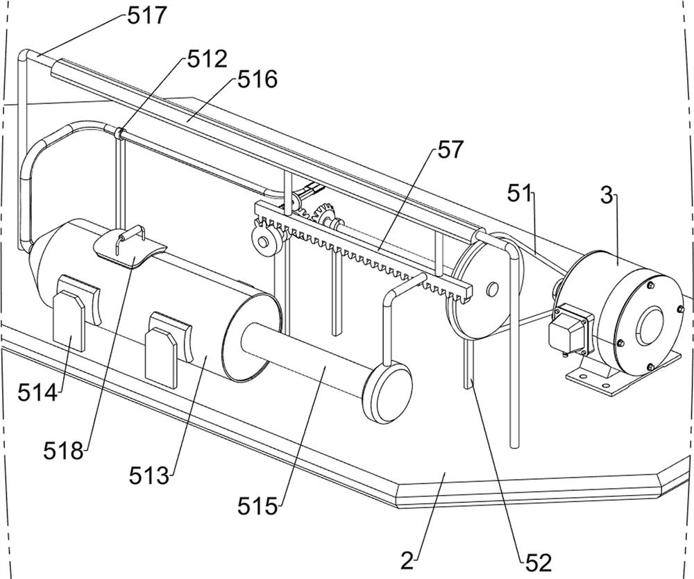
[0027] A car stone automatic grinding device, such as Figure 1-6 As shown, it includes a fixed bracket 1, a workbench 2 and a motor 3. The top of the fixed bracket 1 is connected to a workbench 2, and the left side of the top of the workbench 2 is connected to a motor 3. It also includes a fixed rotation mechanism 4 and a cutting water spray mechanism 5. , the worktable 2 is provided with a fixed rotating mechanism 4 and a cutting water spray mechanism 5 .

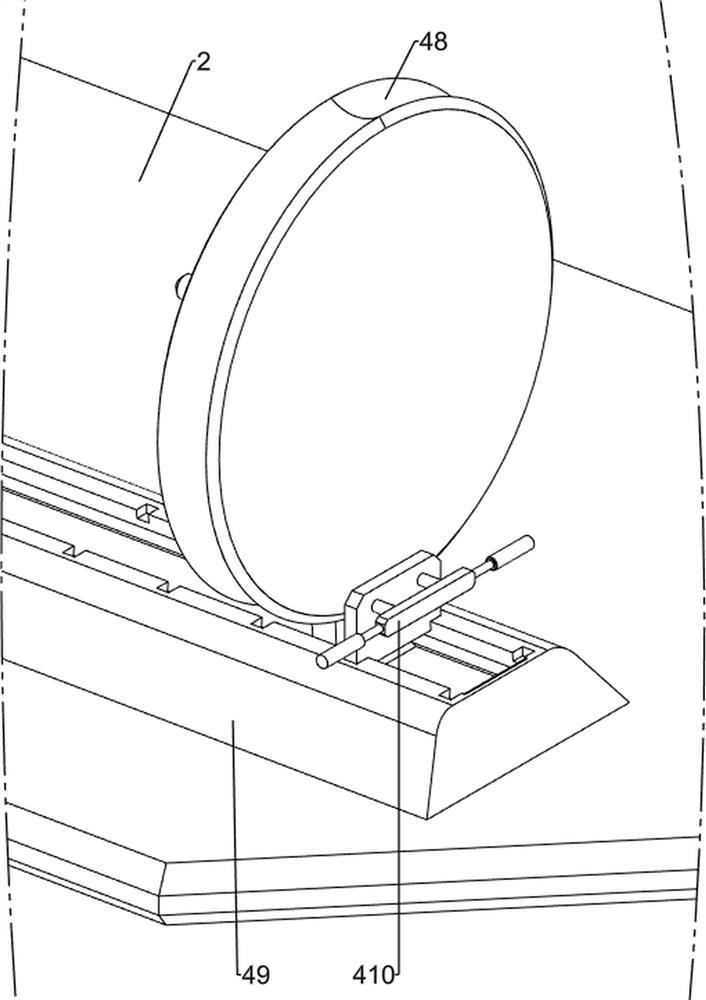
[0028] The fixed rotating mechanism 4 includes a first rotating shaft 41, a first transmission assembly 42, a first bearing column 43, a second rotating shaft 44, a rotating disk 45, a first fixed disk 46, a first spring assembly 47, a second fixed disk 48, The first slide rail 49 and the first baffle 410, the output shaft of the motor 3 is connected with a first rotating shaft 41, the top left side of the worktable 2 is connected with a first bearing column 43, and the first bearing column 43 is rotatably connected with ...

Embodiment 2

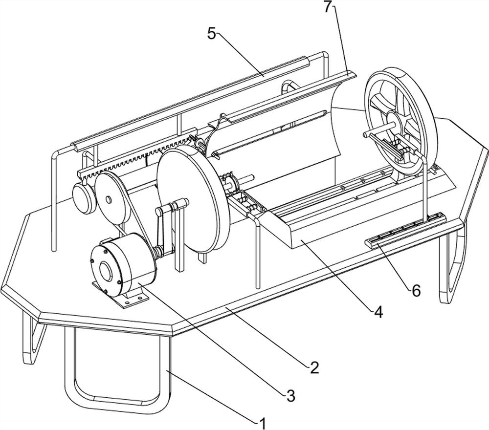
[0032] On the basis of Example 1, as Figure 7 As shown, it also includes a leveling mechanism 6. The leveling mechanism 6 includes a third sliding rail 61, a sliding column 62, a second baffle 63, a third spring assembly 64 and a scraper 65. The top right front side of the workbench 2 is connected with a The third slide rail 61, the left front side of the workbench 2 and the third slide rail 61 are connected with a slide column 62, the slide column 62 on the third slide rail 61 slides with the third slide rail 61, and the third slide rail 61 A second baffle 63 is snap-connected, and the second baffle 63 is detachable. The second baffle 63 is used to block the sliding column 62 on the third sliding rail 61, and the sliding column 62 is slidably connected with a scraper 65. A third spring assembly 64 is connected between the scraper 65 and the sliding column 62 .

[0033] When placing the stone, the two sides of the stone will be in contact with the scrapers 65 on both sides r...


PUM


Abstract

The invention relates to a grinding device, in particular to an automatic grinding device for turning stones. The technical problem to be solved by the present invention is how to design an automatic grinding device for turning stones that can reduce the dust generated during operation, thereby ensuring the environment for workers to operate. In order to solve the above-mentioned technical problems, the present invention provides such an automatic grinding device for turning stones, including: a fixed bracket, the top of which is connected to a workbench; a motor, which is connected to one side of the top of the workbench; a fixed rotation mechanism, which is arranged on On the workbench; the cutting water spray mechanism is arranged on the workbench. In the present invention, the stone is turned through the cooperating operation of the fixed rotation mechanism and the cutting water spraying mechanism, thereby achieving the effect of turning the stone.

Description

technical field [0001] The invention relates to a polishing device, in particular to an automatic polishing device for turning stones. Background technique [0002] Stones generally refer to small rock masses that fall off from large rock masses when they encounter external forces. Most of them are attached to the surface of large rock masses, and are generally block or oval. It can be used to make stone tools and collect stone ore. Thousands of years ago, our ancestors used stones to make fire. Stones are generally composed of calcium carbonate and silica. When the stone is processed, the stone can usually be processed into a cylindrical shape, and the subsequent processing can be performed on the stone. [0003] At present, the method of turning stones is usually to place the stones on the lathe, and then manually operate the lathe to turn the stones. The above method will generate a large amount of dust when turning the stones, and the staff will operate on the side of...

Claims


Application Information

Patent Timeline
Patent Type & Authority Patents(China)
IPC IPC(8): B28D1/16B28D1/22B28D1/00B28D7/02B28D7/00B24B19/22B24B55/06
CPCB28D1/16B28D1/22B28D1/00B28D7/02B28D7/00B24B19/22B24B55/06
Inventor 李平
Owner 临沂临港国有资产运营集团有限公司
Why Eureka
Try Eureka