Limiting mechanism and limiting device

A technology of limit mechanism and limit device, applied in the directions of transportation and packaging, packaging, external frame, etc., can solve the problems of unstable limit and large degree of freedom, so as to improve safety and reliability, increase contact area, limit The effect of safe and stable disassembly

Pending Publication Date: 2020-10-30
QINGDAO TAIPING CONTAINER +1
View PDF0 Cites 0 Cited by
  • Summary
  • Abstract
  • Description
  • Claims
  • Application Information

AI Technical Summary

Problems solved by technology

However, in the prior art, iron chains, steel wire ropes, binding straps, etc. are often used to fasten the steel coils. There is no limit on the end face, and the sides and the circumference of the steel coil are limited by point contact or line contact. The degree of freedom is relatively large, and the limit is unstable. risks of

Method used


Image

  • Limiting mechanism and limiting device
  • Limiting mechanism and limiting device
  • Limiting mechanism and limiting device

Examples


Embodiment 1

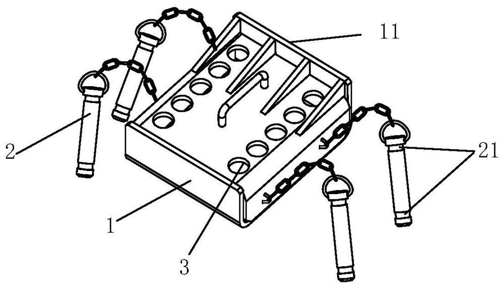
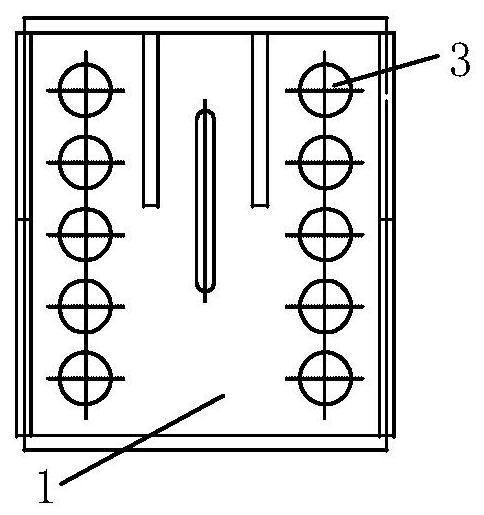
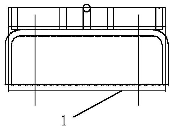
[0068] In this embodiment, the limiting beam 4 and the limiting block 1 are detachable structures. Such as Figure 5 The limiting block 1 is provided with two rows of pin holes 3, each row of pin holes 3 corresponds to two pins 2, the first bearing surface 11 is located at one end of the two rows of pin holes 3, and the limiting block 1 is provided with a limiting plate 12, The limit plate 12 is used to limit the limit block 1 and the upper limit beam 4 . Limiting plate 12 is an upward V-shaped opening made up of two plates. Limiting plate 12 is located between the two rows of pin holes 3 on the limiting block 1. The limiting plate 12 is provided with a third row of pin holes 3. The pins 2 is connected to both sides of the limit block 1 by a chain. Such as Figure 6 A limit beam 4 is shown, the limit beam 4 includes a beam 43, a horizontal plate 44 and a vertical plate 45, wherein the beam 43 is clamped on the horizontal plate 44 through two reinforcing plates 46, and the r...

Embodiment 2

[0070] In this embodiment, the limiting beam 4 and the limiting block 1 are detachable structures. Such as Figure 8 As shown, the limiting block 1 includes two connecting plates 13 at an angle and a receiving plate 14, the two connecting plates 13 are vertically connected to the receiving plate 14, and among the two connecting plates 13, one connecting plate 13 is connected to the base plate 100 is fitted and connected, and the other connecting plate 13 is fitted and connected with the transverse plate 44 of the limit beam 4 . Wherein, the pins 2 are connected by chains on the two connecting plates 13, four pins 2 are connected on the lower connecting plate 13 for pinning the lower connecting plate 13 on the base plate 100, and the connecting pins 2 on the upper connecting plate 13 are used for The limit beam 4 is pinned to the upper connecting plate 3 . The receiving plate 14 is a vertical plate, and when in use, the outer surface of the receiving plate 14 is the first bea...

Embodiment 3

[0073] In this embodiment, the limiting beam 4 and the limiting block 1 are integrally structured. Such as Figure 13 As shown, the outer surface of the receiving plate 14 is the first bearing surface 11, the upper connecting plate 13 of the limiting block 1 and the two ends of the transverse plate 44 of the limiting beam 4 are integrally structured plates, and the transverse beam 43 is fixed by a reinforcing plate 46 On the horizontal plate 44, the rear side of the cross beam 43 is the second bearing surface 41, the vertical plate 45 is connected to the horizontal plate 44 and the rear surface of the vertical plate 45 is coplanar with the rear side of the cross beam 43, and the lower connecting plate of the limiting block 1 The bottom of 13 is provided with pins 2, the arrangement of the pins 2 is the same as the arrangement of the first through hole 1001 on the substrate 100, the lower connecting plate 13 can be directly inserted into the first through hole 1001 and locked t...


PUM


Abstract

The invention belongs to the technical field of mechanical components, and discloses a limiting mechanism and a limiting device. The limiting mechanism comprises a limiting block and a plurality of pins, wherein the limiting block can be fixedly connected onto a baseplate and has a first bearing surface; the first bearing surface can be propped against the end surface of a to-be-limited product carried on the baseplate; the multiple pins are all connected onto the limiting block; locking parts are arranged on all the pins; the pins can be inserted into first through holes of the baseplate; andthe limiting block is fixedly connected onto the baseplate through the locking parts. Through the arrangement of the first bearing surface on the limiting block, the first bearing surface can be utilized for bearing and being propped against the to-be-limited product carried on the baseplate, the limiting contract area can be enlarged, the limiting operation can be safe and stable, and the dismounting operation can be convenient; and through the first bearing surface, the impact force produced by the to-be-limited product during transportation can be better dispersed, and meanwhile, the function of protecting the to-be-limited product can be achieved.

Description

technical field [0001] The invention relates to the technical field of cargo loading and transportation, in particular to a limiting mechanism and a limiting device. Background technique [0002] The steel coil is shaped like a hollow cylinder, which is convenient for storage, transportation and various processing; but because of its large volume, heavy weight and cylindrical shape, it is easy to accumulate load and roll during transportation, especially when it is impacted by the outside world. It is easy to cause instability and damage to transport equipment. [0003] At present, steel coils are mainly loaded vertically, horizontally or clustered vertically during transportation. In order to ensure the safety during transportation, the steel coils need to be fixed at designated positions, so as to avoid damage to the steel coils and various safety issues. Among them, the carbon steel coil is generally installed horizontally. In addition to limiting the two sides to preven...

Claims


Application Information

Patent Timeline
Patent Type & Authority Applications(China)
IPC IPC(8): B65D61/00B65D85/66
CPCB65D61/00B65D85/66
Inventor 林琳袁震齐金祥
Owner QINGDAO TAIPING CONTAINER
Why Eureka
Try Eureka