Conveying belt device with cooling function

A conveyor belt and functional technology, applied in the field of conveyor belt devices with cooling function, can solve problems such as insufficient heat dissipation and cooling effect, single heat dissipation and cooling method, and affect transmission efficiency, etc., to achieve improved heat dissipation and cooling uniformity, effective cooling and heat dissipation, and uniform thickness Effect

Pending Publication Date: 2020-10-30
巢湖市磊成食品有限公司
View PDF0 Cites 1 Cited by
  • Summary
  • Abstract
  • Description
  • Claims
  • Application Information

AI Technical Summary

Problems solved by technology

[0002] Conveyor belts are generally used in a variety of commercial and industrial applications. For the purpose of transporting products and materials, the conveyor belts in the prior art have more functions. There are conveyor belts with a cooling function for cooling the materials on the conveyor belt. Cooling is convenient for subsequent processing or packaging; however, the existing conveyor belt with cooling function has a relatively simple structure, and only a simple fan is used for heat dissipation and cooling. If the cooling effect is low, it is necessary to reduce the transmission rate of the conveyor belt and increase the residence time of the material on the conveyor belt. However, this cooling and heat dissipation method affects the transmission efficiency, so there is no conveyor belt that can improve both the cooling and heat dissipation effect of the material and the transmission efficiency. , so the present invention proposes a conveyor belt device with cooling function to solve the problems in the prior art

Method used


Image

  • Conveying belt device with cooling function
  • Conveying belt device with cooling function
  • Conveying belt device with cooling function

Examples


Embodiment Construction

[0036] In order to deepen the understanding of the present invention, the present invention will be further described below in conjunction with the examples, which are only used to explain the present invention, and do not constitute a limitation to the protection scope of the present invention.

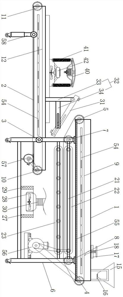
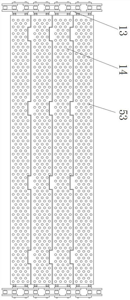
[0037] according to Figure 1-10 As shown, this embodiment proposes a conveyor belt device with a cooling function, including a main frame body 1 and a sub-frame body 2, the rear end of the sub-frame body 2 is hingedly assembled with the main frame body 1 through a first hinge shaft 3 The two ends of the main frame body 1 are equipped with a first driving gear 4 and a second driven gear 5 through bearings, and the upper end of the leg 6 of the main frame body 1 is equipped with a first limit gear 7 and a second gear through a bearing. The limit gear 8, the first driving gear 4, the second driven gear 5, the first limit gear 7 and the second limit gear 8 are equipped with a first conv...


PUM


Abstract

The invention provides a conveying belt device with a cooling function. The device comprises a main frame body and a secondary frame body; the rear end of the secondary frame body is assembled on themain frame body in a hinged mode via a first hinging shaft; a first driving gear and a first driven gear are installed at two ends of the main frame body via bearings; a first limiting gear and a second limiting gear are assembled at the upper ends of supporting legs of the main frame body via bearings; a first conveying belt body is assembled on the first driving gear, the first driven gear, thefirst limiting gear and the second limiting gear; and a second driving gear and a second driven gear are arranged at two ends of the secondary frame body. According to the device, six groups of different structures are arranged with the same function of facilitating heat dissipation and cooling of materials; the structural innovation points are good and the practicability is high; and under a condition of no impact on material conveying efficiency, the material cooling effect is greatly improved, and the device is different to a great extent from existing conveying belt devices with a coolingfunction.

Description

technical field [0001] The invention relates to the technical field of transmission equipment, in particular to a conveyor belt device with a cooling function. Background technique [0002] Conveyor belts are generally used in a variety of commercial and industrial applications. For the purpose of transporting products and materials, the conveyor belts in the prior art have more functions. There are conveyor belts with a cooling function for cooling the materials on the conveyor belt. Cooling is convenient for subsequent processing or packaging; however, the existing conveyor belt with cooling function has a relatively simple structure, and only a simple fan is used for heat dissipation and cooling. If the cooling effect is low, it is necessary to reduce the transmission rate of the conveyor belt and increase the residence time of the material on the conveyor belt. However, this cooling and heat dissipation method affects the transmission efficiency, so there is no conveyor ...

Claims


Application Information

Patent Timeline
IPC IPC(8): B65G47/52B65G69/20
CPCB65G47/52B65G69/20
Inventor 吴磊吴超范红春
Owner 巢湖市磊成食品有限公司
Why Eureka
Try Eureka