Simply supported box girder falling alignment device and using method thereof

An alignment device and simply supported technology, which is applied in bridges, bridge construction, erection/assembly of bridges, etc., can solve the problem of no essential improvement in the effect of accurate alignment

Pending Publication Date: 2020-10-30
CHINA RAILWAY FIFTH SURVEY & DESIGN INST GRP +1
View PDF0 Cites 2 Cited by
  • Summary
  • Abstract
  • Description
  • Claims
  • Application Information

AI Technical Summary

Problems solved by technology

The two drop beam alignment methods and the precise alignment effect have no essential change,

Method used


Image

  • Simply supported box girder falling alignment device and using method thereof
  • Simply supported box girder falling alignment device and using method thereof
  • Simply supported box girder falling alignment device and using method thereof

Examples


Embodiment Construction

[0025] Attached Figure 1~4 To further explain the present invention:

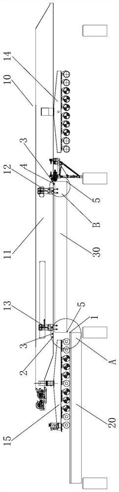
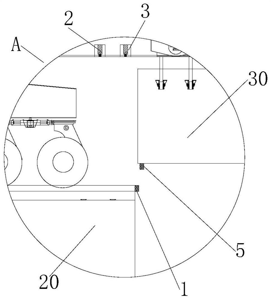
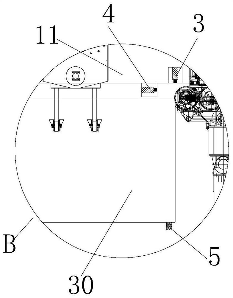
[0026] A simple-supported box girder drop beam alignment device includes a lidar range finder 1 installed at the front end of the simply-supported box girder 20 and beam gap width monitoring on both sides of the lower surface of the main beam 11 of the bridge erector 10 Instrument 2, the beam gap width monitor 2 is located above the rear end of the simply supported box beam 30 to be erected. The beam gap width monitor 2 is provided with at least two positions on both sides of the lower surface of the main beam 11, and the light path direction of the beam gap width monitor 2 faces the rear end of the simply supported box beam 30 to be erected. The video image collected by the slit width monitor 2 roughly estimates the distance between the simply supported box girder 30 to be erected and the simply supported box girder 20 that has been erected, and then controls the front hanging beam trolley 12 and the rear h...


PUM


Abstract

The invention relates to the field of high-speed railway construction, and provides a simply supported box girder falling alignment device and a using method thereof. The simply-supported box girder falling alignment device comprises a laser radar range finder arranged at the front end of an erected simply-supported box girder and girder seam width monitors arranged on the two sides of the lower surface of a main girder of a bridge girder erection machine, and the girder seam width monitors are located above the rear end of the simply-supported box girder to be erected. The distance between the to-be-erected simply supported box girder and the erected simply supported box girder is estimated according to a video image acquired by the girder seam width monitor; then, the front hanging beamtrolley and the rear hanging beam trolley are controlled to enable the to-be-erected simply supported box girder to be close to the erected simply supported box girder; the to-be-erected simply supported box girder is controlled to descend slowly in the next step; the laser radar range finder starts to collect the actual distance between the to-be-erected simply supported box girder and the end face of the erected simply supported box girder; and the front hanging beam trolley and the rear hanging beam trolley are controlled again to enable the to-be-erected simply supported box girder to moveforwards or backwards to keep a distance required by the design with the erected simply supported box girder, so that girder falling alignment of the to-be-erected simply supported box girder can becompleted.

Description

Technical field [0001] The invention belongs to the field of high-speed railway construction, and specifically designs a simple-supported box beam drop beam alignment device and a use method thereof. Background technique [0002] At present, most of China's high-speed railway prestressed concrete simply supported box girders are prefabricated 24m, 32m and 40m prestressed concrete simply supported box girder in beam yard. The erection of 24m, 32m and 40m simply supported box girder generally adopts transportation. For the erection method of a separated frame or an integrated machine for transport and erection, the prior art bridge erector 10 includes a main beam 11 on which a front beam trolley 12 for lifting a simply supported box beam 30 to be erected and a rear crane The girder trolley 13, the front end and the rear end of the main girder 11 of the integrated bridge erecting machine are provided with a front car 14 and a rear car 15, respectively, and the front end and the rear...

Claims


Application Information

Patent Timeline
IPC IPC(8): E01D21/00E01D2/04
CPCE01D2/04E01D21/00
Inventor 周衍领万鹏杨建福罗九林陆慧郭春晖蒋中明谌启发梁志新王治斌周光忠
Owner CHINA RAILWAY FIFTH SURVEY & DESIGN INST GRP
Why Eureka
Try Eureka