
Deep foundation pit side wall steel mold trolley traction device

A technology for a steel form trolley and a traction device, which is applied to shaft equipment, infrastructure engineering, artificial islands, etc., can solve the problems of long on-site construction occupation time, large economic investment, and difficulty in installation and dismantling of steel form trolleys.

Pending Publication Date: 2020-10-30
SINOHYDRO BUREAU 14 CO LTD
View PDF0 Cites 0 Cited by
  • Summary
  • Abstract
  • Description
  • Claims
  • Application Information

AI Technical Summary

Problems solved by technology

[0005] In order to overcome the reciprocating hoisting of the concrete steel formwork trolley for the side wall of the deep foundation pit in the background technology, the on-site construction takes a long time, which affects the construction progress of the site, and there are many potential safety hazards in the construction process, and the on-site construction of the steel formwork trolley is safe. It is difficult to disassemble and cause a large economic investment. The invention provides a deep foundation pit side wall steel form trolley traction device, which can save costs, shorten the construction period, and produce better social and economic benefits; scope of application Wide, economical and applicable, strong feasibility, high utilization rate, can improve construction efficiency, simple processing, convenient construction, high site flexibility, maximum reuse, and minimize the potential safety hazards in site construction

Method used


Image

  • Deep foundation pit side wall steel mold trolley traction device
  • Deep foundation pit side wall steel mold trolley traction device

Examples


Embodiment 1

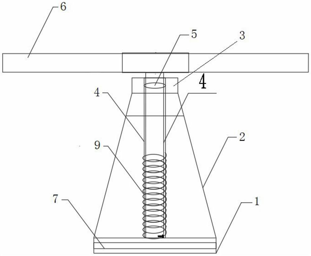
[0015] Embodiment 1: as Figure 1-2 As shown, the traction device of the steel mold trolley for the side wall of the deep foundation pit includes a lower base 1, a bracket 2, an upper base 3, a rotating shaft 4, a bearing 5, a rotating handle 6, square wood 7, and a steel wire rope 9, and the base 1 is fixed on the ground. , the bracket 2 is a four-sided truss-shaped bracket, the bracket 2 is fixed on the base 1, the upper base 3 is fixed on the top of the bracket 2, the bearing 5 is installed in the upper base 3, the bottom end of the rotating shaft 4 is movable on the lower base 1, and the top of the rotating shaft 4 wears The bearing 5 is fixedly connected with the rotating handle 6; one end of the 6*19 steel wire rope 9 is wound on the rotating shaft, and the other end is connected with the side wall steel mold trolley 8, and two square timbers 7 are arranged at the bottom of the lower base 1; the lower base is It is welded by 800mm long L250×90×9×13L-shaped steel. The fra...


PUM


Abstract

The invention discloses a deep foundation pit side wall steel mold trolley traction device. The device comprises a lower base, a support, an upper base, a rotating shaft, a bearing, a rotating handle,wooden blocks and a steel wire rope. The base is fixed to the ground. The support is a support in a quadrangular table shape, and the support is fixed to the base. The upper base is fixed to the topof the support. The bearing is mounted in the upper base. The bottom end of the rotating shaft is movably arranged on the lower base. The top end of the rotating shaft penetrates through the bearing to be fixedly connected with the rotating handle. One end of the steel wire rope is wound on the rotating shaft, and the other end of the steel wire rope is connected with a side wall steel mold trolley. The two or more wooden blocks are arranged at the bottom of the lower base. Materials of the device are obtained from materials left or wasted in field construction, waste is turned into wealth infield, the materials can be repeatedly used, and the device is simple in machining operation and high in speed; and in the construction process, flexibility is high, field practicality is high, the safety of surrounding construction personnel can be protected to the largest extent, cost is saved, the building construction period is shortened, and good social and economic benefits are generated.

Description

technical field [0001] The invention belongs to the technical field of municipal civil engineering, and in particular relates to a fast and convenient pulling device for a steel mold trolley for the side wall of a deep foundation pit. Background technique [0002] Nowadays, in the construction process of the main structure of the subway station, most of the concrete pouring of the side walls of deep foundation pits in China uses steel formwork trolleys, but the construction progress is slow. Major hidden danger. The above-mentioned construction method is very common in the construction site at our site. However, with the continuous improvement of the construction progress of the foundation pit and the continuous increase of construction machinery and labor costs, the above-mentioned construction process will greatly increase the construction investment. The reciprocating demolition and installation not only require a large amount of manpower, but also seriously affect the s...

Claims


Application Information

Patent Timeline
IPC IPC(8): E02D29/045E21D11/10
CPCE02D29/04E21D11/10
Inventor 赵康康付艳军邹德海马克乾景勇梁子潇李雷杨云祥李鹏毫刘子杰
Owner SINOHYDRO BUREAU 14 CO LTD
Learn More