
Tension end joint structure of laminated T-beam wing plate under assembled building plate and construction method

A construction method and beam and wing plate technology, which are applied in building structures, building components, buildings, etc., can solve the problems of low hoisting speed and accuracy, difficult building construction, and high hoisting costs, and achieve good anti-negative bending moment effect of nodes, Strong anti-seismic ability, the effect of improving the mechanical characteristics

Inactive Publication Date: 2020-10-30
江苏永坤建设有限公司
View PDF7 Cites 2 Cited by
  • Summary
  • Abstract
  • Description
  • Claims
  • Application Information

AI Technical Summary

Problems solved by technology

Traditional prefabricated structures have high hoisting costs and low hoisting speed and precision, which brings great difficulties to building construction. If the hoisting of prefabricated buildings wants to realize industrial modernization, the hoisting methods and detailed structural design of connection nodes must be paid attention to. Need for further innovative research

Method used


Image

  • Tension end joint structure of laminated T-beam wing plate under assembled building plate and construction method

Examples


Embodiment 1

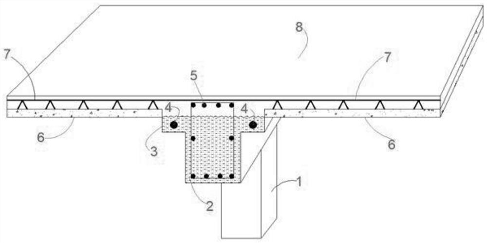
[0037] The present invention is a tension end node structure of laminated T-beam wing plates under assembled building panels, comprising: PC structural columns 1, PC laminated T-beams 2, prestressed reinforcement tunnels 4, superimposed T-beam upper extension steel bars 5, Laminated slab 6, truss bars 7 of laminated slab and overall post-cast concrete surface 8; PC laminated T beam 2 is arranged above PC structural column 1; PC laminated T beam 2 is provided with prestressed reinforcement channel 4, PC The upper part of the T beam 2 is provided with an outstretched steel bar 5, and a laminated plate 6 is provided above the PC laminated T beam 2; a laminated plate truss bar 7 is arranged above the laminated plate 6, and the extended steel bar 5 is fixedly connected with the laminated plate truss bar 7; An integral post-cast concrete surface layer 8 is provided above the truss bar 7 of the laminated slab.

[0038] In order to further explain this embodiment, it should be noted t...

Embodiment 2

[0043] A construction method for the tension end node structure of the superimposed T-beam wing plate under the assembled building slab, characterized in that the specific steps are:

[0044] a. On-site hoisting construction of PC structural column 1;

[0045] b. On-site hoisting construction of PC laminated T-beam 2;

[0046] c. Reinforcement sleeve grouting connection at the post-casting section of beam-column joints and erection of formwork supports;

[0047] d. Tensioning and anchoring of unbonded prestressed tendons at the end of PC laminated T-beam 2 slabs;

[0048]e. On-site hoisting of the prefabricated laminated slab 6, the overhanging steel bar 5 on the upper part of the laminated T beam of the prefabricated laminated slab 6 is fixedly connected to the truss bar 7 of the adjacent laminated slab at the cross beam;

[0049] f. Binding of longitudinal steel bars on the upper part of the laminated slab 6, and overall construction of the post-cast concrete surface;

[...


PUM


Abstract

The invention discloses a tension end joint structure of a laminated T-shaped beam wing plate under an assembled building plate. The tension end joint structure comprises a PC structural column, a PClaminated T-shaped beam, a prestressed steel bar hole channel, an outward-extending steel bar at the upper part of the laminated T-shaped beam, a laminated plate, a laminated plate truss rib and an integral post-cast concrete surface layer; the PC laminated T beam is arranged above the PC structural column; the prestressed steel bar hole channel is formed in the PC laminated T beam, the outward-extending steel bar is arranged on the upper part of the PC laminated T beam, and the laminated plate is arranged above the PC laminated T beam; the laminated plate truss rib is arranged above the laminated plate, and the outward-extending steel bar is fixedly connected with the laminated plate truss rib; and the integral post-cast concrete surface layer is arranged above the laminated plate truss rib. According to the tension end joint structure, the under-plate integrated laminated T-beam wing plate end prestress tension technology is adopted at the fabricated concrete beam-column joint, the stress characteristic of the beam-column joint is effectively improved, the hogging moment resisting effect of the joint is good, and the seismic capacity of the prestressed beam-column reinforced joint is high.

Description

technical field [0001] The invention relates to a tension end node structure and construction method of a superimposed T-beam wing plate under an assembled building plate. Background technique [0002] In recent years, with the continuous development and progress of new building technologies and materials, prefabricated buildings have been widely used. In many countries with developed building industrialization, prefabricated buildings have experienced long-term experiments and applications. Modern prefabricated building products can already highly integrate various functions of buildings, and the forms and components of buildings are very delicate. my country's construction demand is large and the construction speed is fast. It is necessary to develop prefabricated buildings, so the requirements for the construction of prefabricated structural nodes and hoisting technology are also getting higher and higher. Traditional prefabricated structures have high hoisting costs and...

Claims


Application Information

Patent Timeline
Patent Type & Authority Applications(China)
IPC IPC(8): E04B5/43E04B1/22E04B5/38E04G21/12
CPCE04B1/22E04B5/38E04B5/43E04G21/12
Inventor 李维民陈征李建德李静
Owner 江苏永坤建设有限公司
Learn More