Straight claw rotor

A technology of straight claw claw and rotor, applied in the direction of rotary piston pump, rotary piston machine, rotary piston engine, etc., can solve the problem of incomplete meshing of the back line of the claw.

Inactive Publication Date: 2016-12-21
CHINA UNIV OF PETROLEUM (EAST CHINA)
View PDF8 Cites 2 Cited by
  • Summary
  • Abstract
  • Description
  • Claims
  • Application Information

AI Technical Summary

Problems solved by technology

[0004] In order to solve the above problems, the present invention proposes a straight-claw claw-type rotor and a construction method. A section of cycloid EF is smoothly connected with the second claw-tip arc DE and line segment FG at the back of the claw, and the claw-type rotor claw back is realized. The full meshing at the position solves the problem of incomplete meshing of the claw back line; the claw rotor profile can not only achieve the correct meshing of all p

Method used


Image

  • Straight claw rotor
  • Straight claw rotor
  • Straight claw rotor

Examples


Embodiment Construction

[0048] The present invention will be further described below in conjunction with the accompanying drawings and embodiments.

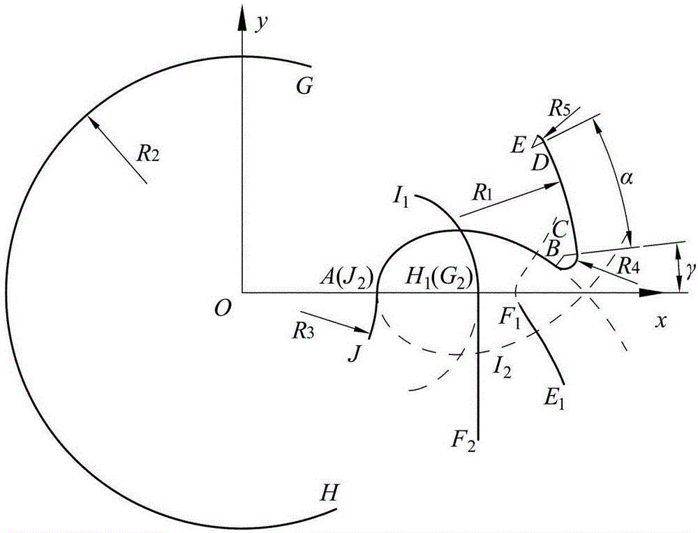
[0049] Such as figure 1 As shown, it is the generation process of the profile of a straight-claw rotor proposed. According to the equations of each profile, each profile is directly generated: pitch circle arc GH, envelope H of the initial line segment 1 I 1 , the isometric curve I of the initial cycloid 2 J 2 , claw bottom arc JA, cycloid equidistant curve AB, first claw tip arc BC, claw top arc CD, second claw tip arc DE, initial cycloid E 1 f 1 , the initial segment F 2 G 2 ;

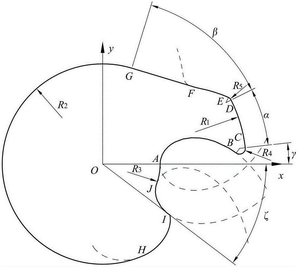
[0050] Such as figure 2 As shown, it is a proposed straight claw rotor, which consists of 5 arcs (BC, CD, DE, GH, JA), 2 equidistant curves of cycloids (AB, IJ), and 1 cycloid (EF), a line segment (FG) and an envelope line (HI) of a line segment are connected, and the claw rotor constituted by the junction of the envelope line HI of the except line segment and the eq...


PUM


Abstract

The invention discloses a straight claw rotor which comprises ten curves: five arcs, two equidistant curves of a cycloid, a cycloid, a line segment and an envelope line of the line segment; the pitch circle arc GH, the envelope line HI of the line segment, the equidistant curve IJ of the cycloid, the claw foot arc JA, the equidistant curve AB of the cycloid, the first claw tip arc BC, the claw top arc CD, the second claw tip arc DE, the cycloid EF and the line segment FG are sequentially connected counterclockwise from a pitch circle; and all the other molded lines are smoothly connected except for a connection point I of the envelope line HI of the line segment and the equidistant curve IJ of the cycloid. two mutually engaged claw rotors are identical; all the molded lines of the claw rotor can be engaged correctly during working; the problem that a claw back curve does not participate in engagement completely is solved; and the working efficiency and working performance of a claw fluid machine are improved.

Description

technical field [0001] The invention relates to a straight claw claw rotor. Background technique [0002] Claw type fluid machinery is a new type of dry fluid machinery widely used in petrochemical, aerospace, semiconductor industry and other fields. It realizes the suction, compression and discharge of gas through the synchronous and opposite double-rotation motion of a pair of conjugated rotors. , the performance of the claw fluid machinery depends on the claw rotor, so the design of the rotor profile is the core issue of the claw fluid machinery. [0003] The meshing characteristics of the claw rotor profile directly determine the working performance of the claw rotor. The existing straight claw claw rotor profile includes: 3 arcs, 2 cycloids, 1 line, and the envelope of 1 line Wire. Chinese patent (patent number: ZL201110308963.4) proposes a claw rotor, which is composed of 5 circular arcs and 3 cycloid equidistant curves, which realizes the meshing of the rotor curves...

Claims


Application Information

Patent Timeline
IPC IPC(8): F04C18/12F04C25/02F01C1/12F01C21/08
CPCF01C1/126F01C21/08F04C18/126F04C25/02
Inventor 王君崔冬刘瑞青张凌宏刘强魏蜀红
Owner CHINA UNIV OF PETROLEUM (EAST CHINA)
Why Eureka
Try Eureka