
Blade

A blade and auxiliary blade technology, applied in the field of fan blade design, can solve the problems of high cost, frequent activation of the speed-limiting mechanism, large loss, etc., and achieve the effects of improving stress, increasing resistance, and reducing wind speed.

Pending Publication Date: 2020-10-30
葛文星
View PDF0 Cites 0 Cited by
  • Summary
  • Abstract
  • Description
  • Claims
  • Application Information

AI Technical Summary

Problems solved by technology

However, when the wind speed is uneven and the speed of the fan blades is uneven, the speed limiting mechanism will start frequently, resulting in large losses and high costs.

Method used


Image

  • Blade
  • Blade
  • Blade

Examples


Embodiment 1

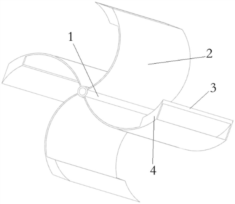
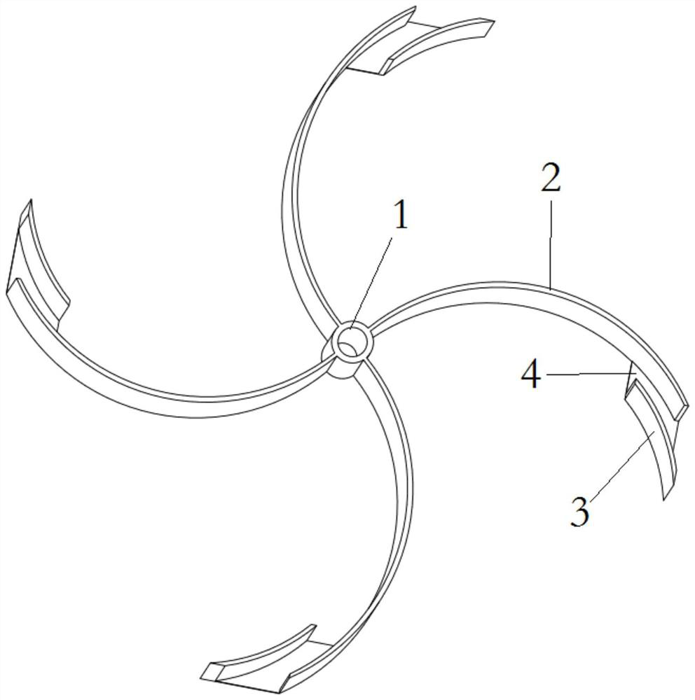
[0024] like figure 1 and figure 2 As shown, a blade includes a mandrel 1 and a sheet body 2, the sheet body 2 is evenly distributed around the mandrel 1 in the circumferential direction and the tail end of the sheet body is fixedly connected to the mandrel 1, and the head end of the sheet body 2 is provided with Auxiliary blade 3 , the shape of which is the equidistant surface of the corresponding sheet body; both ends of the auxiliary blade are fixedly connected to the sheet body through bracket 4 .

Embodiment 2

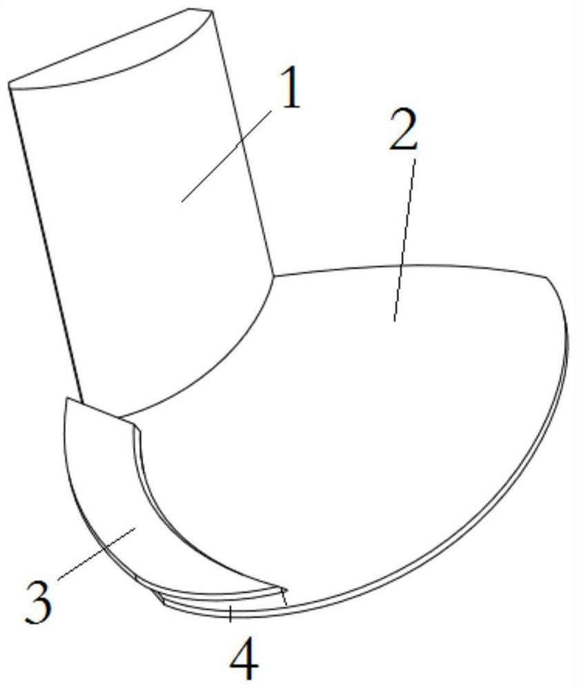
[0026] like image 3 As shown, a blade includes a mandrel 1 and a sheet body 2, the sheet body 2 is evenly distributed around the mandrel 1 in the circumferential direction and the tail end of the sheet body is fixedly connected to the mandrel 1, and one side of the sheet body 2 is provided with There are auxiliary blades 3, and the shape of the auxiliary blades 3 is the equidistant surface of the corresponding sheet body part; the two ends of the auxiliary blades are fixedly connected with the sheet body through the bracket 4.

Embodiment 3

[0028] In this embodiment, the stand is an electric folding stand. The main function of using the electric folding bracket is to open the auxiliary blade when needed to form a channel with the sheet body, and to form a folded shape between the auxiliary blade and the sheet body when not needed to reduce resistance.

[0029] Figure 4 The structure of one type of electric bracket is shown. Specifically, the bottom and top of the two brackets 4 are respectively hinged with the sheet body and the auxiliary blade 3, and the sheet body is respectively provided with a The fixed pulley 5, the mandrel 1 is provided with a forward and reverse motor 6, and the rotating shaft is provided with a wire wheel 7, and the wire wheel is provided with a winding wire, and the two ends of the winding wire are outgoing, and one end of the outgoing wire is fixed to the auxiliary blade through a fixed pulley connection, the other end of the outgoing line is fixedly connected to the auxiliary blade t...


PUM


Abstract

The invention relates to the field of a fan blade design, and discloses a blade. The blade comprises a core shaft and blade bodies, wherein the blade bodies are uniformly distributed around the circumferential direction of the core shaft, and the end parts of the tail edges of the blade bodies are fixedly connected with the core shaft; a back blade is arranged on the front or the back of at leastone of other three edge parts of each blade body, and the shape of the back blade is the equidistant surface of the corresponding blade body part; and the two ends of the back blade are connected withthe core shaft or the corresponding blade body through supports. The invention also provides a deceleration blade, and a back blade is arranged on the leeward side of a blade body. The blade has thebeneficial effects that the stress condition of the blade is improved; when the blade is arranged on the front of a windward side, the area of the forward stress surface of the blade and the instantaneous wind speed can be improved, so that forward thrust is provided, and the blade can also rotate and work normally in light and weak wind conditions; and when the blade is arranged on the back of the windward side, the resistance can be increased, so that the blade is stabilized, and the wind speed is reduced.

Description

technical field [0001] The invention relates to the field of fan blade design, in particular to a blade. Background technique [0002] Wind blades are commonly used components in wind power generation systems. Existing wind blades are mostly set with multiple blade ring mandrels, and the blades rotate under force to drive the mandrel to rotate, and then generate power; usually for better force bearing, the blades are usually designed is a curved surface. Because the load of the power generation system is usually relatively large, the windward side of the existing blade structure can rotate when the wind is strong, but it does not rotate in the case of light wind, resulting in idle equipment and ineffective use of resources. [0003] In addition, the greater the wind force of the fan blades in the existing structure, the faster its speed will be. When the speed exceeds a certain speed, it needs to limit the speed, otherwise it will cause damage to the power generation system...

Claims


Application Information

Patent Timeline
IPC IPC(8): F03D3/06
CPCF03D3/062Y02E10/74
Inventor 葛文星赵志强高俊李树宏邓小光蒋国涛刘书雨
Owner 葛文星
Learn More